|
Size: 10348
Comment:
|
Size: 10488
Comment:
|
| Deletions are marked like this. | Additions are marked like this. |
| Line 159: | Line 159: |
| Be aware that in case of a static sensor (i.e. no tf information) the normal vectors are simply pointing towards the sensor at any time. |
| |
Getting Started with ECHO ONE
Description: Using the Toposens stack to connect to and display data from Toposens 3D ultrasonic sensorsKeywords: Toposens, ECHO ONE, TS3, ultrasound
Tutorial Level: BEGINNER
Contents
This tutorial assumes that either Ubuntu 16.04 with ROS Kinetic or Ubuntu 18.04 with ROS Melodic is used.
Install Driver
Depending on the ROS distribution that you are using, install the binaries of the Toposens ROS packages with the following command:
sudo apt install ros-<distro>-toposens
E.g. if you are using ROS Melodic, it would look like this:
sudo apt install ros-melodic-toposens
Alternative: Build Driver from Source
As an alternative to installing the binaries, you could also compile the packages from source. In order to follow the steps below, you need to have a catkin workspace and catkin tools installed.
Clone the toposens metapackage into the source folder of your catkin workspace:
cd ~/catkin_ws/src
git clone https://gitlab.com/toposens/public/ros-packages.git
Use rosdep to install missing dependencies:
rosdep update
rosdep install --from-paths ~/catkin_ws/src/ros-packages/ --ignore-src --rosdistro <distro> -y
In your catkin workspace build the package by using catkin build:
cd ~/catkin_ws
catkin build toposens
Source your build space:
source ~/catkin_ws/devel/setup.bash
This needs to be done in every new terminal or you can add this command to your bashrc for it to be executed automatically when opening a new terminal window.
Enable Serial Port Permissions
Add yourself to the “dialout” group:
sudo adduser $USER dialout
Trigger updated group permissions to take effect:
newgrp dialout
Re-login or reboot for the updated group permissions to take effect permanently.
Connect TS3 Sensor
Connect your Toposens TS3 sensor via the provided USB cable (for TS3 versions v1.0 & v1.1: FTDI cable) to any available USB port on your computer.
Obtain the connected terminal ID for the device:
dmesg | grep "cp210x" | tail -n 1 | awk 'NF{print $NF}'For TS3 v1.0 & v1.1:
dmesg | grep "FTDI" | tail -n 1 | awk 'NF{print $NF}'In the case below, the terminal ID would be ttyUSB0 
Visualize Data
There are three different ways of viewing the data output from a TS3 sensor, which are published to three separate topics:
/ts_scans broadcasts messages of type toposens_msgs/TsScan, which hold the raw data stream parsed as toposens_msgs
/ts_markers broadcasts messages of type visualization_msgs/MarkerArray for simple visualization with RViz
/ts_cloud broadcasts messages of type sensor_msgs/PointCloud2, which can be visualized in RViz and also logged to a file
The utility of these topics is further explored in the following sections.
View Raw Stream
The ts_driver_node translates the sensor data into custom toposens_msgs/TsScan messages.
Launch the driver node and start accruing data from a TS3 sensor. Set the corresponding serial port as launch argument (here: /dev/ttyUSB0):
roslaunch toposens_driver toposens_driver.launch port:=/dev/ttyUSB0
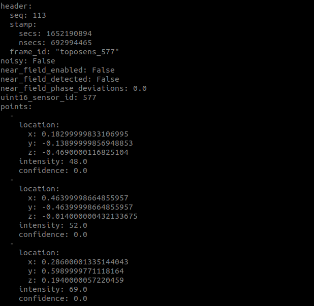
The sensor data is published to the the topic /ts_scans. View the incoming scans with:
rostopic echo /ts_scans

Visualize Data as Markers
The ts_markers_node translates the messages of type toposens_msgs/TsScan into messages of type visualization_msgs/MarkerArray, which can be visualized in RViz.
The driver node as well as the markers node are launched from within one launch-file:
roslaunch toposens_markers toposens_markers.launch port:=/dev/ttyUSB0
The markers are visualized in RViz: ![]()
View Pointcloud in RViz
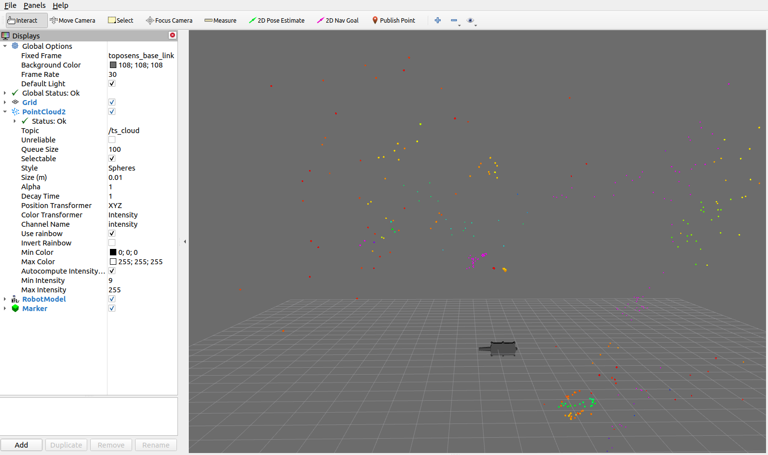
The ts_cloud_node translates the messages of type toposens_msgs/TsScan into messages of type sensor_msgs/PointCloud2.
Since version 2.0 the package makes use of the standard PointCloud type PointXYZINormal instead of the custom type TsPoint. |
Due to the specular reflection behavior of ultrasound, the surface normal of the detected object can be represented by a vector pointing from the detected point towards the sensor’s position while the point was recorded. This normal vector is added to the PointCloud representation. For a more detailed explanation of the physics behind Toposens sensors see Physics of 3D Ultrasonic Sensors.
The driver node as well as the pointcloud node are launched from within one launch-file:
roslaunch toposens_pointcloud toposens_cloud.launch port:=/dev/ttyUSB0
The pointcloud is visualized in RViz: 
In order to visualize the surface normal vectors as well run the launch-file with the corresponding argument:
roslaunch toposens_pointcloud toposens_cloud.launch port:=/dev/ttyUSB0 lifetime_normals_vis:=1.0
Be aware that in case of a static sensor (i.e. no tf information) the normal vectors are simply pointing towards the sensor at any time.
The pointcloud is logged to the file ~/catkin_ws/src/ros-packages/toposens_pointcloud/toposens.pcd
Manipulate Parameters
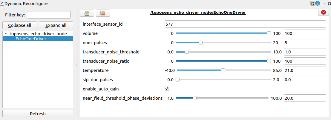
To manipulate sensor parameters as well as visualization parameters live in realtime, run in an additional terminal window:
rosrun rqt_reconfigure rqt_reconfigure
The ts_driver_node respectively ts_markers_node need to be running for this to work.
Sensor Parameters
There are 6 different parameters that can be changed in the ts_driver_node.

Variable Name |
Description |
num_pulses |
This is the only parameter that has an effect on the emitted ultrasonic signal. It defines the number of electrical pulses that the piezo transmitter is stimulated with in every transmission cycle. The higher the number, the louder and longer the emitted signal will be. As a result, increasing the value will detect objects that are further away, decreasing it will increase the sensor's precision in short range. |
echo_rejection_threshold |
This parameter defines the minimum amplitude, i.e. the signal strength, that a received echo signal needs to have in order to be utilized for further processing. Signals that are below this threshold are discarded. As a result, increasing the value will ignore more points of smaller intensity and only allow strong reflectors to be detected. |
peak_detection_window |
This parameter defines the kernel size for a peak detection filter that is applied on the received ADC signals in order to find the peaks that link to the echoes of the detected objects. When it is set too high, objects that are close to each other might merge to one bigger object. Decreasing it might separate these objects but might also destabilize the resulting signal. |
noise_indicator_threshold |
This parameter has no effect on the visualization of the pointcloud or the markers. It is solely used to mark individual scans with a noise flag. This is done by calculating an overall noise level for the raw ADC signal of one frame. If this noise level lies above the noise_indicator_threshold, the noise flag for this scan is set. This might indicate that there are sources of ultrasonic disturbances in the scene. However the scans will be shown regardless of the noise flag. |
external_temperature |
This parameter defines the temperature that is used for calculating the speed to sound. Its accuracy has an effect on the correct calculation of the distance of objects. The value is only used if use_external_temperature is checked. |
use_external_temperature |
The TS3 also has an on-board temperature sensor. If use_external_temperature is not checked, the TS3 will use its on-board temperature sensor for speed-of-sound calculation. If it is checked, it will use the external_temperature. |
Marker Parameters
There are 2 parameters that can be changed in the ts_markers_node.
Variable Name |
Description |
lifetime |
Duration for which a marker should remain visible |
scale |
Magnitude for resizing markers equally and simultaneously |


