|
Size: 11443
Comment:
|
Size: 9683
Comment:
|
| Deletions are marked like this. | Additions are marked like this. |
| Line 74: | Line 74: |
| == Create a roslaunch file == For simplicity sake, you'll be using roslaunch. Start creating a roslaunch file: `calib.launch` The file should have the following structure: {{{ <launch> <node pkg="rxtools" name="rxconsole" type="rxconsole"/> |
== Setting up the image processing == Modify the roslaunch file `calib.launch` to add the following lines: {{{ <launch> ... |
| Line 84: | Line 83: |
| <node pkg="visp_camera_calibration" name="visp_camera_calibration_image_processing" type="visp_camera_calibration_image_processing"> | <node pkg="visp_camera_calibration" name="visp_camera_calibration_image_processing" type="visp_camera_calibration_image_processing" args="camera_prefix:=/camera"> |
| Line 88: | Line 87: |
| Line 95: | Line 92: |
| You'll fill in the details later. == Setting up the pattern == |
The camera_prefix argument used in the previous lines indicates that image_raw from camera /camera will be processed. == Setting up the calibration grid pattern == |
| Line 106: | Line 103: |
<launch> <node pkg="rxtools" name="rxconsole" type="rxconsole"/> |
<launch> ... |
| Line 110: | Line 106: |
| <node pkg="visp_camera_calibration" name="visp_camera_calibration_calibrator" type="visp_camera_calibration_calibrator"/> | <node pkg="visp_camera_calibration" ... /> |
| Line 112: | Line 108: |
| <node pkg="visp_camera_calibration" name="visp_camera_calibration_image_processing" type="visp_camera_calibration_image_processing"> <param name="gray_level_precision" value="0.7" /> <param name="size_precision" value="0.5" /> <param name="pause_at_each_frame" value="False" /> |
<node pkg="visp_camera_calibration" ... > ... |
| Line 129: | Line 123: |
<launch> <node pkg="rxtools" name="rxconsole" type="rxconsole"/> |
<launch> ... |
| Line 133: | Line 126: |
| <node pkg="visp_camera_calibration" name="visp_camera_calibration_calibrator" type="visp_camera_calibration_calibrator"/> | <node pkg="visp_camera_calibration" ... /> |
| Line 135: | Line 128: |
| <node pkg="visp_camera_calibration" name="visp_camera_calibration_image_processing" type="visp_camera_calibration_image_processing"> <param name="gray_level_precision" value="0.7" /> <param name="size_precision" value="0.5" /> <param name="pause_at_each_frame" value="False" /> |
<node pkg="visp_camera_calibration" ... > ... |
| Line 144: | Line 135: |
| <!-- 3D coordinates of all points on the calibration pattern. In this example, points are planar --> <rosparam param="model_points_x">[0.0, 0.03, 0.06, 0.09, 0.12, 0.15, 0.0, 0.03, 0.06, 0.09, 0.12, 0.15, 0.0, 0.03, 0.06, 0.09, 0.12, 0.15, 0.0, 0.03, 0.06, 0.09, 0.12, 0.15, 0.0, 0.03, 0.06, 0.09, 0.12, 0.15, 0.0, 0.03, 0.06, 0.09, 0.12, 0.15]</rosparam> <rosparam param="model_points_y">[0.0, 0.00, 0.00, 0.00, 0.00, 0.00, .03, 0.03, 0.03, 0.03, 0.03, 0.03, .06, 0.06, 0.06, 0.06, 0.06, 0.06, .09, 0.09, 0.09, 0.09, 0.09, 0.09, 0.12,0.12, 0.12, 0.12, 0.12, 0.12, 0.15,0.15, 0.15, 0.15, 0.15, 0.15]</rosparam> <rosparam param="model_points_z">[0.0, 0.00, 0.00, 0.00, 0.00, 0.00, 0.0, 0.00, 0.00, 0.00, 0.00, 0.00, 0.0, 0.00, 0.00, 0.00, 0.00, 0.00, 0.0, 0.00, 0.00, 0.00, 0.00, 0.00, 0.00, 0.00, 0.00, 0.00, 0.00, 0.00, 0.0, 0.00, 0.00, 0.00, 0.00,0.00]</rosparam> |
|
| Line 160: | Line 147: |
| * the console | * The console |
| Line 184: | Line 171: |
| rosservice call visp_camera_calibration/calibrate 2 0.5 640 480 | rosservice call visp_camera_calibration/calibrate 2 640 480 |
| Line 188: | Line 175: |
| * 0.5 is the visual servoing static gain |
| |
Calibration of an external camera using the ViSP library
Description: This tutorials is a step by step guide which shows how to define your calibration pattern, model. Then it discusses camera calibration using the ViSP library. Finally, it will briefly walk you through the calibration results.Keywords: visp camera calibration
Tutorial Level: INTERMEDIATE
Contents
Before starting
Make sure you have the following:
- A ROS-compatible camera driver. You can use the experimental visp_camera_calibration_camera node for this.
A calibration pattern. You can print the pattern used in the lagadic laboratory.
- A 3D model of your grid.
- A reasonably well-lit space to display the calibration pattern from various angles.
Compiling
Start by getting the dependencies and compiling the package.
rosdep install visp_camera_calibration
rosmake visp_camera_calibration
Set up
Camera
Plug in your camera and install the corresponding ROS package to be able to grab images.
If your camera is firewire install the camera1394 package. For simplicity sake, start creating a roslaunch file: calib.launch. To grab and display images from this camera it should have the following structure:
<launch>
  <!-- % rxconsole -->
  <node pkg="rxtools" name="rxconsole" type="rxconsole"/>
  <!-- % rosrun camera1394 camera1394_node -->
  <node pkg="camera1394" type="camera1394_node" name="my_camera1394_node"/>
  <!-- % rosrun image_view image_view image:=/camera/image_raw -->
  <node pkg="image_view" type="image_view" name="my_image_raw_viewer" args="image:=/camera/image_raw"/>
</launch>
Make sure your camera is publishing on the topic image_raw. This is a standard ROS topic for cameras. You can check this by doing:
rostopic list
Setting up the image processing
Modify the roslaunch file calib.launch to add the following lines:
<launch>
        ...
        <group ns="visp_camera_calibration">
                <node pkg="visp_camera_calibration" name="visp_camera_calibration_calibrator" type="visp_camera_calibration_calibrator"/>

                <node pkg="visp_camera_calibration" name="visp_camera_calibration_image_processing" type="visp_camera_calibration_image_processing" args="camera_prefix:=/camera">
                      <param name="gray_level_precision" value="0.7" />
                      <param name="size_precision" value="0.5" />
                      <param name="pause_at_each_frame" value="False" />
                </node>
        </group>
</launch>
The camera_prefix argument used in the previous lines indicates that image_raw from camera /camera will be processed.
Setting up the calibration grid pattern
Print your pattern on way you have the biggest contrast to make tracking easier. Your pattern should be set of points. Measure and/or enter the 3D coordinates of your points in the object frame. Chances are you printed the pattern on a piece of paper; if so, all your points will have the same Z coordinate.
Fill the model definition into the lauch file. To do so, you'll have to set define three parameters, each one corresponding to a point coordinate (X,Y or Z). You need to do that for each point:
<launch>
        ...
        <group ns="visp_camera_calibration">
                <node pkg="visp_camera_calibration"  ... />

                <node pkg="visp_camera_calibration"  ... >
                      ...

                      <!-- 3D coordinates of all points on the calibration pattern. In this example, points are planar -->
                      <rosparam param="model_points_x">[0.0, 0.03, 0.06, 0.09, 0.12, 0.15, 0.0, 0.03, 0.06, 0.09, 0.12, 0.15, 0.0, 0.03, 0.06, 0.09, 0.12, 0.15, 0.0, 0.03, 0.06, 0.09, 0.12, 0.15, 0.0, 0.03, 0.06, 0.09, 0.12, 0.15, 0.0, 0.03, 0.06, 0.09, 0.12, 0.15]</rosparam>
                      <rosparam param="model_points_y">[0.0, 0.00, 0.00, 0.00, 0.00, 0.00, .03, 0.03, 0.03, 0.03, 0.03, 0.03, .06, 0.06, 0.06, 0.06, 0.06, 0.06, .09, 0.09, 0.09, 0.09, 0.09, 0.09, 0.12,0.12, 0.12, 0.12, 0.12, 0.12, 0.15,0.15, 0.15, 0.15, 0.15, 0.15]</rosparam>
                      <rosparam param="model_points_z">[0.0, 0.00, 0.00, 0.00, 0.00, 0.00, 0.0, 0.00, 0.00, 0.00, 0.00, 0.00, 0.0, 0.00, 0.00, 0.00, 0.00, 0.00, 0.0, 0.00, 0.00, 0.00, 0.00, 0.00, 0.00, 0.00, 0.00, 0.00, 0.00, 0.00, 0.0, 0.00, 0.00, 0.00, 0.00,0.00]</rosparam>
                </node>
        </group>
</launch>
You also need to select a smaller number (4 for example) of points on your model. These points will be the starting point for pose estimations. Write these points to the xml file the same way you wrote the model definition:
<launch>
        ...
        <group ns="visp_camera_calibration">
                <node pkg="visp_camera_calibration" ... />

                <node pkg="visp_camera_calibration" ... >
                      ...
                      <!-- 3D coordinates of 4 points the user has to select to initialise the calibration process -->
                      <rosparam param="selected_points_x">[0.03, 0.03, 0.09, 0.12]</rosparam>
                      <rosparam param="selected_points_y">[0.03, 0.12, 0.12, 0.03]</rosparam>
                      <rosparam param="selected_points_z">[0.00, 0.00, 0.00, 0.00]</rosparam>

                </node>
        </group>
</launch>
Running the calibration
To start the calibration, just type:
roslaunch calib.launch
Three nodes will be launched (besides the camera):
- The console
- The calibrator node which will stay silent
- The image processing interface node with which you will interact.
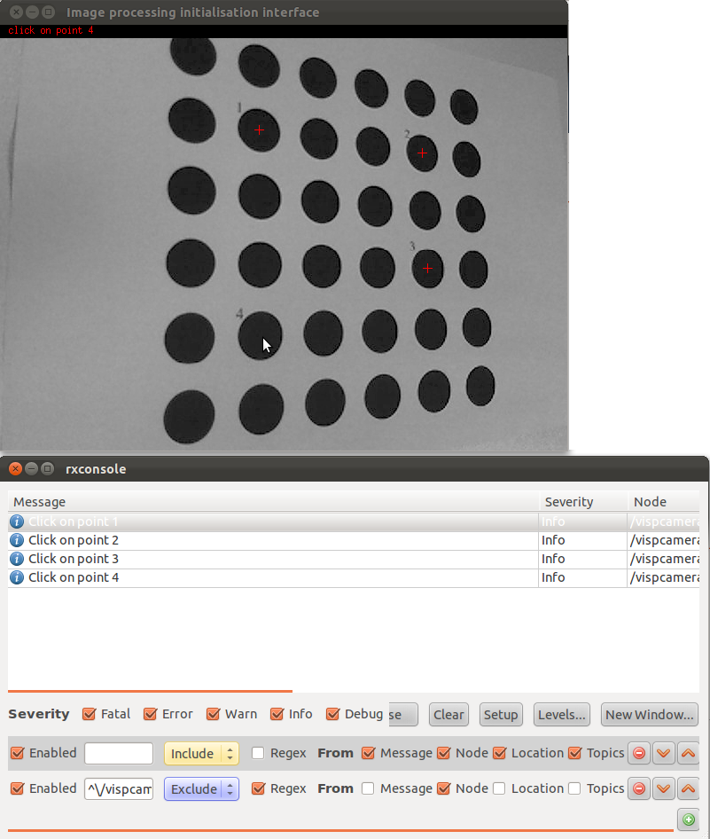
In the rxconsole, you will see instructions about how to proceed and information about the calibration process. Some information will also be shown as red text over the images.
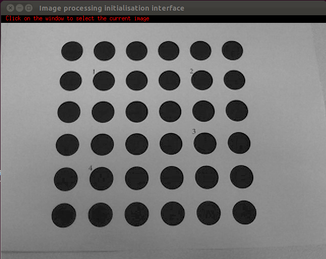
Move the printed pattern somewhere in the field of view of the camera. The image should appear: 
When you are ready, click anywhere on the window. Once you have clicked, you need to select points in the window called "image processing initialisation interface". Select the special points you defined earlier in the xml file. 
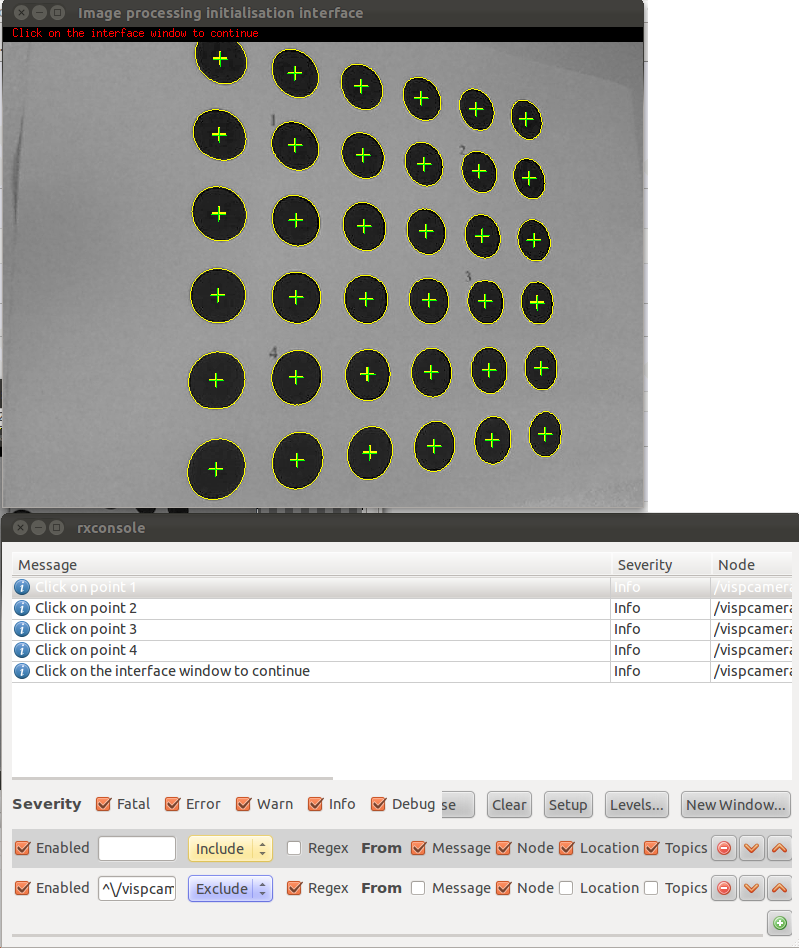
When the four points are selected, the image processing interface will try to detect the rest of the points. Your grid should look like this:  Then, click on the interface window again and repeat the process until you have processed enough samples.
The calibrator node now has enough information to compute the new camera parameters. You are now ready to call the calibration service.
Calibrating
In a new terminal type:
rosservice call visp_camera_calibration/calibrate 2 640 480
Those parameters may not seem intuitive to you, here is a quick overview:
2 is a code refering to a calibration model with distorsion (see model codes)
- 640 and 480 are the width and height of the image.
Calibration Results
You should have the following output:
stdDevErrs: [0.754157558996595, 0.7077502995027428, 0.7352593181329484, 0.7899300419694113]
stdDevErrsDist: [0.43714855418957455, 0.5039971167151152, 0.4991662359530044, 0.4800084572634955]
Since the requested model has distorsions, only stdDevErrsDist, the standard deviations w/r to the distorted model make sense. The quantities are expressed in pixels and should be reasonably low.
The node will then attempt to set the calculated camera info to the calibrated camera. If possible, it will also write a calibration.ini file (in your $HOME/.ros directory) containing the calibration parameters in the INI format:
# Camera intrinsics

[image]

width
640

height
480

[image_raw]

camera matrix
548.83913 0.00000 309.68288
0.00000 541.05367 246.39086
0.00000 0.00000 1.00000

distortion
-0.01019 0.00000 0.00000 0.00000 0.00000


rectification
1.00000 0.00000 0.00000
0.00000 1.00000 0.00000
0.00000 0.00000 1.00000

projection
548.83913 0.00000 309.68288 0.00000
0.00000 541.05367 246.39086 0.00000
0.00000 0.00000 1.00000 0.00000
Links to go further
Once you've obtained the camera parameters, you can load them into your camera and use them to rectify your image. Standard ROS cameras are able to load yml or ini calibration files by using the camera_info_manager package. This may be simplified with a graphical user interface. Check the camera1394 package and the dynamic reconfigure package to see how to graphically load camera parameters into the camera node.
Once the camera is configured you should use the image_proc package to rectify the image, as indicated in the following tutorial.


