Distance measurement with ultrasonic sensor HC-SR04 using the Arduino with an I2C connection (Python)
This tutorial guides you through wiring a HC-SR04 ultrasonic sensor to an Arduino Nano and connect this via an I2C connection to a Raspberry Pi. A distance to an object can then be measured by a run-time measurement.
Before starting you should read What is a ROS Wrapper?, Write a ROS Wrapper (Python) and Package and Test Your Driver.
In this project, an ultrasonic sensor module (HC-SR04) is put into operation. The working principle of an HC-SR04 is explained. It is also described how a measurement with ultrasound works and on which essential factors it depends. For the commissioning of the sensor, we take an I2C connected Arduino to a Raspberry Pi as an example.
What is ultrasonic?
Ultrasound is a high-pitched sound wave whose frequency exceeds the audible range of human hearing.

Humans can hear sound waves that vibrate in the range of about 20 times a second (a deep rumbling noise) to 20,000 times a second (a high-pitched whistle). However, ultrasound has a frequency of more than 20,000 Hz and is therefore inaudible to humans.
What is an ultrasonic sensor?
An ultrasonic sensor is generally a sensor that determines the distance to an object via a run-time measurement. It cannot classify which object is located at this distance. As shown in the following figure, the ultrasonic sensor emits ultrasonic waves. This is where it gets its name. At an object, these ultrasonic waves are reflected and reflected back. A membrane on the sensor receives these ultrasonic waves. Since it is known how fast the carrier medium is, a distance to the object is determined based on the time interval between sending and receiving the ultrasonic waves. We will take a closer look at what this means in concrete terms below.
The HC-SR04 sensor
An HC-SR04 ultrasonic distance sensor actually consists of two ultrasonic transducers. Ultrasonic transducers and ultrasonic sensors are devices that generate or sense ultrasound energy. They can be divided into three broad categories: transmitters, receivers and transceivers. Transmitters convert electrical signals into ultrasound, receivers convert ultrasound into electrical signals, and transceivers can both transmit and receive ultrasound.
The HC-SR04 sensor looks like this:
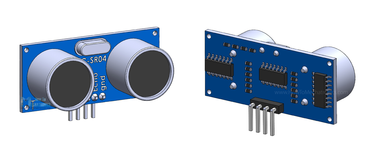
One acts as a transmitter that converts the electrical signal into 40 KHz ultrasonic sound pulses. The other acts as a receiver and listens for the transmitted pulses.
When the receiver receives these pulses, it produces an output pulse whose width is proportional to the distance of the object in front.
This sensor provides excellent non-contact range detection between 2 cm to 400 cm (~13 feet) with an accuracy of 3 mm.
Since it operates on 5 volts, it can be connected directly to a Raspberry Pi or any other 5V logic microcontroller.
Technical Specifications
Operating Voltage |
DC 5V |
Operating Current |
15mA |
Operating Frequency |
40KHz |
Max Range |
4m |
Min Range |
2cm |
Ranging Accuracy |
3mm |
Measuring Angle |
15 degree |
Trigger Input Signal |
10µS TTL pulse |
Dimension |
45 x 20 x 15mm |
Pinout
Let’s take a look at its pinout.
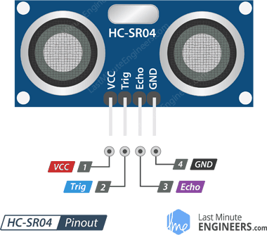
VCC supplies power to the HC-SR04 ultrasonic sensor. You can connect it to one of the 5V outputs from your Raspberry Pi.
Trig (Trigger) pin is used to trigger ultrasonic sound pulses. By setting this pin to HIGH for 10µs, the sensor initiates an ultrasonic burst.
Echo pin goes high when the ultrasonic burst is transmitted and remains high until the sensor receives an echo, after which it goes low. By measuring the time the Echo pin stays high, the distance can be calculated.
GND is the ground pin. Connect it to the ground of your Raspberry Pi.
Operating principle
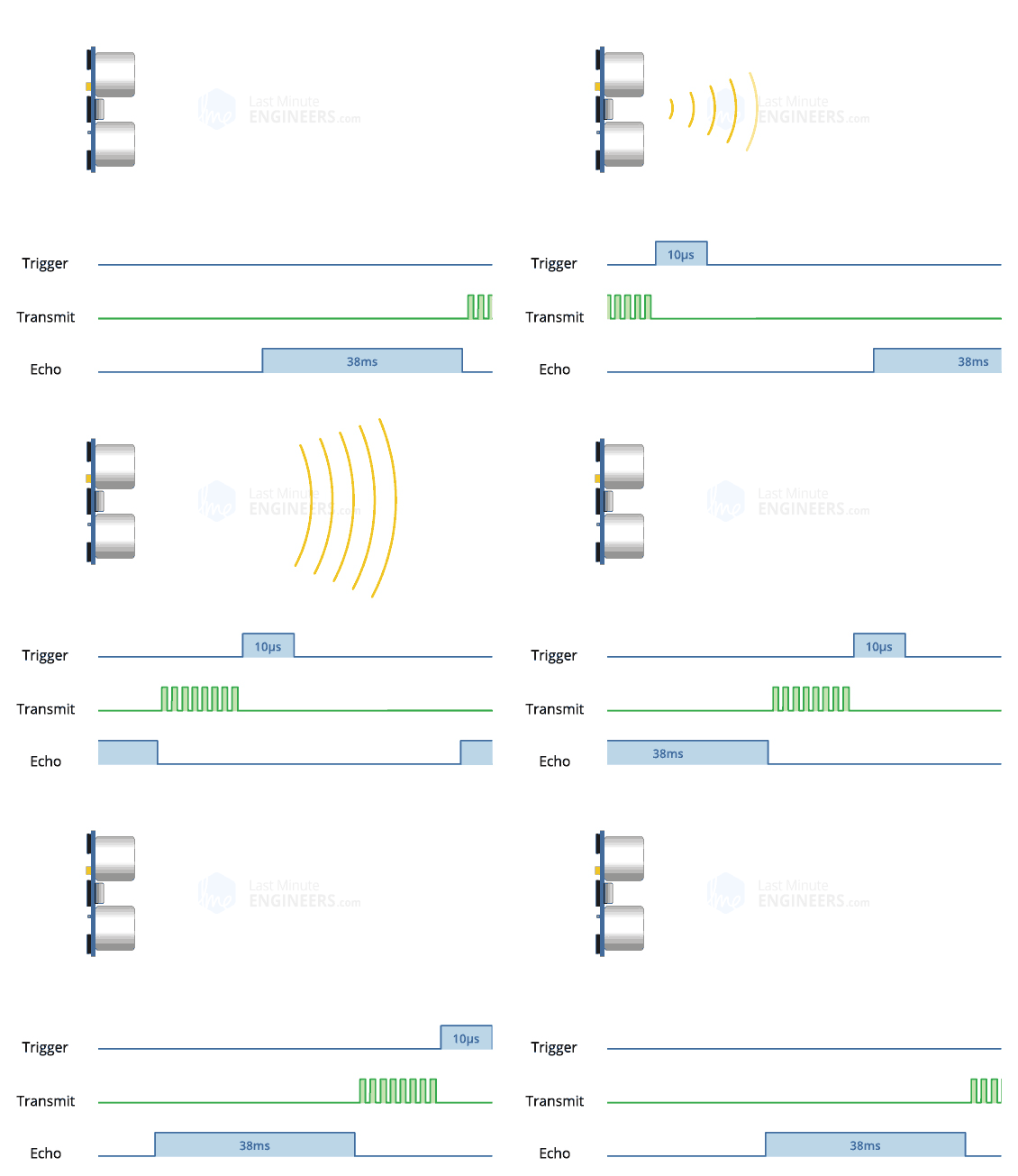
It all starts when the trigger pin is set HIGH for 10µs. In response, the sensor transmits an ultrasonic burst of eight pulses at 40 kHz. This 8-pulse pattern is specially designed so that the receiver can distinguish the transmitted pulses from ambient ultrasonic noise.
These eight ultrasonic pulses travel through the air away from the transmitter. Meanwhile the echo pin goes HIGH to initiate the echo-back signal.
If those pulses are not reflected back, the echo signal times out and goes low after 38ms (38 milliseconds). Thus a pulse of 38ms indicates no obstruction within the range of the sensor.
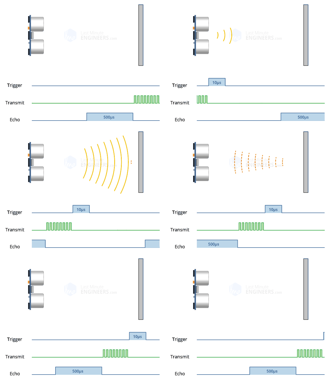
If those pulses are reflected back, the echo pin goes low as soon as the signal is received. This generates a pulse on the echo pin whose width varies from 150 µs to 25 ms depending on the time taken to receive the signal.
Calculating the distance
The width of the received pulse is used to calculate the distance from the reflected object. This can be worked out using the simple distance-speed-time equation we learned in high school. An easy way to remember the equation is to put the letters in a triangle.
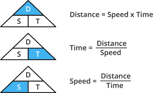
Let us take an example to make it more clear. Suppose we have an object in front of the sensor at an unknown distance and we receive a pulse of 500µs width on the echo pin. Now let’s calculate how far the object is from the sensor. For this we will use the below equation.
Distance = Speed x Time
Here we have the value of time i.e. 500 µs and we know the speed. Of course it’s the speed of sound! It is 340 m/s. To calculate the distance we need to convert the speed of sound into cm/µs. It is 0.034 cm/μs. With that information we can now calculate the distance!
Distance = 0.034 cm/µs x 500 µs
But we’re not done yet! Remember that the echo pulse indicates the time it takes for the signal to be sent and reflected back. So to get the distance, you have to divide your result by two.
Distance = (0.034 cm/µs x 500 µs) / 2
Distance = 8.5 cm
Now we know that the object is 8.5 cm away from the sensor.
How to wire the HC-SR04 and the Arduino to the Raspberry Pi?
Please have a look at the following diagram:
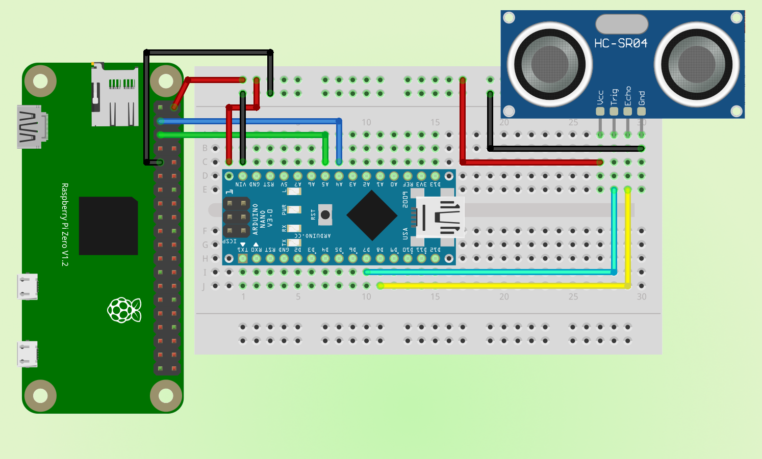
Admittedly, in the illustration we see a Raspberry Pi Zero and an Arduino NANO, but both the different Raspberry Pis and the different Arduinos are identical in construction. So we could wire up a Raspberry Pi 3 Model B+ and an Arduino UNO in the same way.
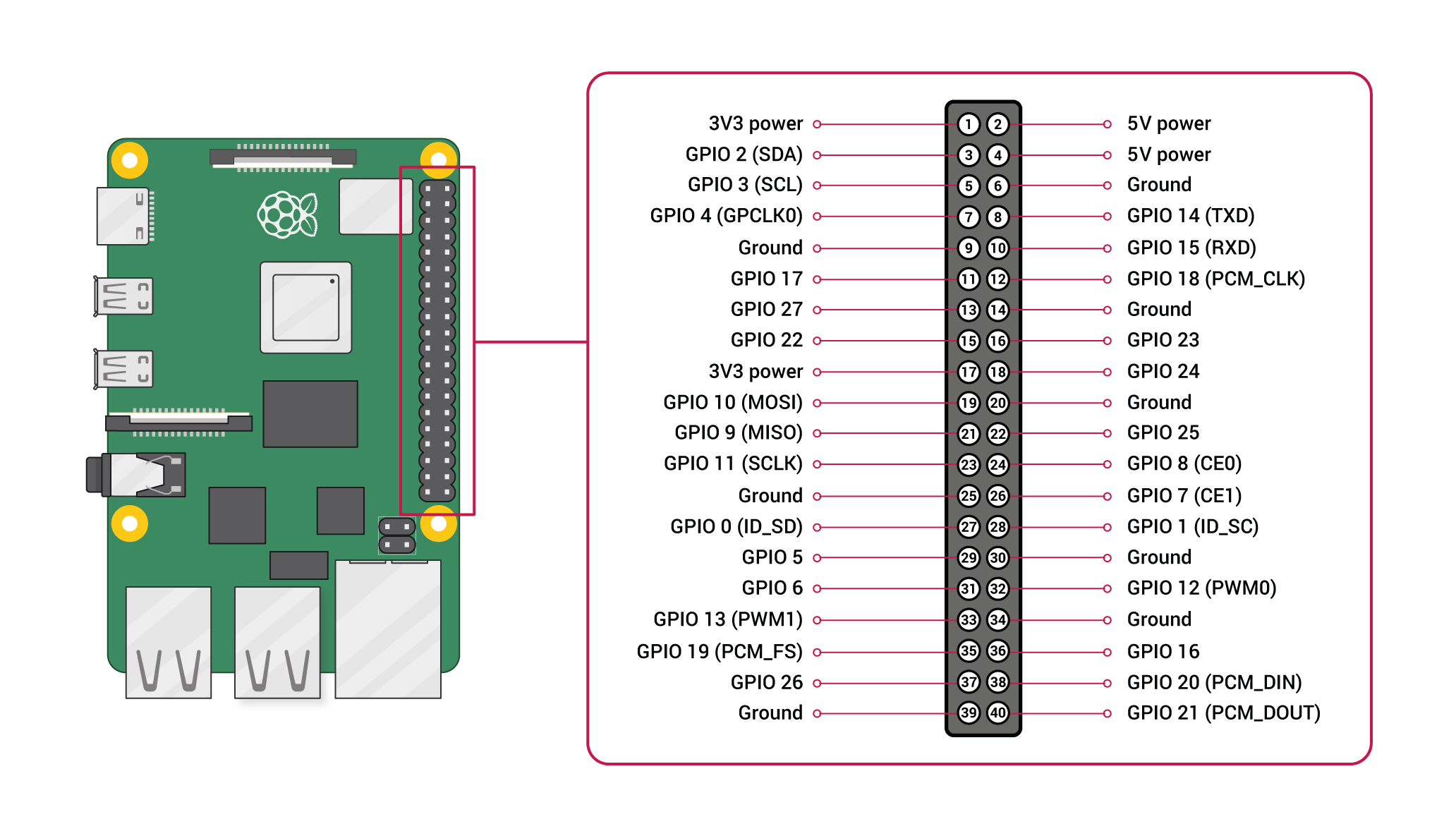
This is how the pinout of the Raspberry Pi looks like:
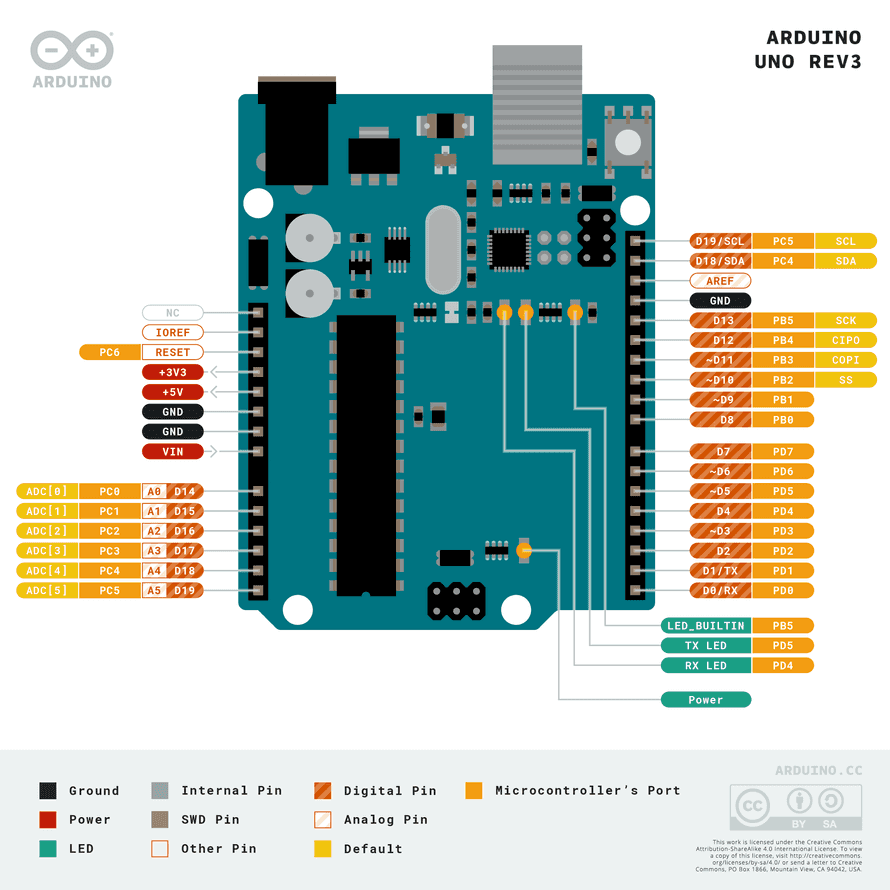
And this is how the pinout of the Arduino looks like:
The structure is such that the Arduino serves as a driver board for the sensor and over I2C forwards the data to the Raspberry Pi, since it runs ROS. With this example it will be explained how driver boards are used to connect hardware components. In robotics there are often boards for motors or servo motors.
Both the Arduino and the Raspberry Pi enable an I2C bus. First, we supply power to the Arduino from the Raspberry Pi. For this we connect pin 2 (5V) to the VIN of the Arduino, we also connect the GND together (for example pin 9 on the Raspberry Pi). In the picture above, both cable connections on the Arduino have accidentally slipped one place too far to the left. On the Arduino NANO the A5 pin also stands for SCL and the A4 pin for SDA. SDA stands for Serial Data. The line for the master and slave to send and receive data. SCL stands for Serial Clock. The line that carries the clock signal. I2C is a serial communication protocol, so data is transferred bit by bit along a single wire (the SDA line). So we connect pin 3 (SDA) of the Raspberry Pi to A4 of the Arduino and pin 5 (SCL) to A5. Now the Raspberry Pi and the Arduino are connected via I2C and can communicate accordingly. Depending on the programming, the Raspberry Pi can be the master and the Arduino the slave or vice versa.
In our case, the Raspberry Pi will ultimately be the master and the Arduino the slave, which will operate our sensor. After that we have to connect the HC-SR04 to the Arduino. For this we also get the 5V from the Raspberry Pi and ground the sensor with it. This is because we also supply the Arduino with power via the Raspberry Pi. Then we can immediately connect the sensor to the original source at the current flow. We connect the trigger pin to D7 and the echo pin to D8.
This leads to the following constellation:
Raspberry Pi |
Arduino |
Pin 2 (5V) |
VIN |
Pin 3 (SDA) |
A4 (SDA) |
Pin 5 (SCL) |
A5 (SCL) |
Pin 6 or Pin 9 (GND) |
GND |
In our example we now connect the HC-SR04 to our Arduino. I have used the Arduino NANO for this:
HC-SR04 |
Arduino |
Trigger |
D7 |
Echo |
D8 |
And we connect the ground and voltage to our Raspberry Pi because the Raspberry Pi will at least power the Arduino and the Arduino:
Raspberry Pi |
HC-SR04 |
Pin 2 (5V) |
VCC |
Pin 6 or Pin 9 (GND) |
GND |
Unlike the Raspberry Pi, we now no longer need to use a voltage divider. This is because the Arduino works with 5V instead of 3.3V on its digital pins.
Preparations on the Raspberry Pi
=== Activating the I2C bus with raspi-config ====
To enable I2C we have to activate the interface in the kernel. This can easily be done with the Raspberry Pi configuration tool raspi-config.
sudo raspi-config
In the interface we navigate to Advanced Options - I2C.
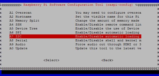
Pressing the Enter key activates I2C. You are asked if you want to activate the ARM I2C interface and if the I2C kernel module should be loaded automatically at system start. We confirm both with Yes.
In addition, the configuration tool points out that the settings only become active after a reboot and offers to reboot the system now. We also confirm this with Yes and restart the system. In principle, I2C is now enabled on the Raspberry Pi.
Manually activating the I2C bus
The following also explains how to manually enable the serial bus interface on the Pi and make it usable.
To manually enable I2C on the Raspberry Pi we need to load the I2C kernel module at boot time. For this we edit the file /etc/modules.
sudo nano /etc/modules
We enter the I2C kernel modules into the file and then save the file.
i2c-bcm2708
i2c-dev
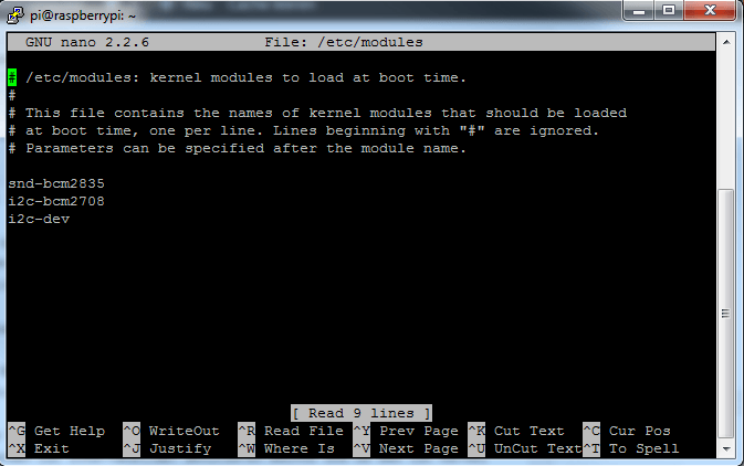
Furthermore the file /boot/config.txt can be opened and checked for the correct content.
sudo nano /boot/config.txt
You should find the following two lines at the end of the file. Otherwise we add them and save and close the configuration file.
dtparam=i2c1=on
dtparam=i2c_arm=on
Finally we edit the file /etc/modprobe.d/raspi-blacklist.conf. This file contains modules which are not loaded during operation, i.e. no entries for I2C may be contained here. The following lines must not be in the file or must be commented out by prepending the # character per line so that I2C becomes active.
# blacklist spi and i2c by default
# blacklist spi-bcm2708
# blacklist i2c-bcm2708
After we have manually made the settings to enable I2C on the Raspberry Pi, the single board computer must be rebooted for the settings to become active.
sudo reboot
Testing the I2C bus
After we have activated the I2C interface on the Raspberry Pi using raspi-config or manually, we can test if it works. With the help of the tool i2cdetect, the serial bus is scanned for connected devices, such as sensors or similar. In a table the connected devices become recognizable. For this we first install the I2C toolkit.
sudo apt-get install i2c-tools
sudo i2cdetect -y 1
Also install smbus for python2 (there are other libraries available but I haven’t looked into them yet)
sudo apt-get install python-smbus
or for python3
pip3 install smbus2
Programming the distance measurement
At this point we need to program two things: An Arduino Sketch that ultimately performs the measurement on the Arduino and writes the data serially, and a Python program on the Raspberry Pi that reads the serially written data.
The Arduino Sketch
The Arduino Sketch looks like this:
#include

#define SLAVE_ADDRESS 0x04
#define TRIGGER 4
#define ECHO 5

byte latest[4] = {0,0,0,0};
bool ready = true;
int count = 0;

void HCSR04() {
    ready = false;
    // Clear trigger
    digitalWrite(TRIGGER,LOW);
    delayMicroseconds(2);

    // send 10 microseond trigger
    digitalWrite(TRIGGER, HIGH);
    delayMicroseconds(10);
    digitalWrite(TRIGGER, LOW);

    // time to get echo
    long timeElapsed = pulseIn(ECHO, HIGH);

    // calculate distance
    float distance = float(timeElapsed) / 1000000 / 2 * 34300;
    union {
        float a;
        unsigned char bytes[4];
    } thing;
    thing.a = distance;
    memcpy(latest, thing.bytes, 4);
    ready = true;
}

// callback for sending data
void sendData(){
    Wire.write(0x00);
    Wire.write(latest[count++]);
    if (count==4) {
        count=0;
    }
}

void setup() {
    // initialize i2c as slave
    Wire.begin(SLAVE_ADDRESS);

    // define callback for i2c communication
    Wire.onRequest(sendData);

    pinMode(TRIGGER, OUTPUT);
    pinMode(ECHO, INPUT);
}

void loop() {
    HCSR04();
}
Remember we will use the address 0x04.
The Python Code
On the Raspberry Pi we can query the sensor information like this:
import traceback
import struct
import smbus2

bus = smbus2.SMBus(1)

# This is the address we setup in the Arduino Program
address = 0x04

try:
    b = []
    for byt in range(4):
        b.append(bus.read_byte(address))

    distance = struct.unpack("f", bytearray(b))[0]

    print(distance)

except KeyboardInterrupt:
    # User stopped
    print("\nBye...")

except:
    # If something goes wrong
    traceback.print_exc()
It’s a basic loop that reads 4 bytes at a time into an array and then unpacks it.
We have learned how to handle the pins on the Arduino to send an output once and to receive an input once. The output refers to the TRIG pin of the sensor. The trigger signal is an ultrasonic wave that the sensor sends out. For the echo coming back, we use the ECHO pin of the sensor. This pin now refers to the input. Since we know the speed of sound (carrier medium), we determine a time interval between the start time when we release the trigger and the arrival time when the echo comes back. This is called a run-time measurement. What we also learned is how to write the data from the Arduino serially using the I2C bus, as well as how to read and receive this data from the Raspberry Pi.
In the next chapter, we'll look at Speed measurement with ultrasonic sensor HC-SR04 using the Arduino with an I2C connection (Python).


