| Note: This tutorial assumes that you have completed the previous tutorials: Creating a nxt robot. |
| |
Creating a simple robot model using lxf2urdf.py
Description: This tutorial demonstrates how to convert a Lego Digital Designer file (*.lxf and *.ldr) to a ROS robot model file (*.urdf).Tutorial Level: BEGINNER
Contents
Getting the Files
For this tutorial we'll be using the robot.lxf and robot.ldr files from the nxt_robot_kit_test package. You can directly download them from this page or grab them from the nxt_robot_kit_test package.
Generating the URDF
nxt_lxf2urdf.py converts the Lego Digital Designer file to unified robot description format (urdf) that ROS uses for robot models. Copy the robot.lxf and robot.ldr files to your learning_nxt package that you created in the previous tutorial. Now run lxf2urdf.py on the robot.lxf and robot.ldr file and output the result into robot.urdf.
$ rosrun nxt_lxf2urdf lxf2urdf.py robot.lxf robot.ldr >robot.urdf
Now that we have created a urdf file let's look at the result and see what edits are needed for a finished robot model.
Visualizing the Result
In your learning_nxt package edit your robot.launch file to include the following lines at the top (in between the <launch> and </launch> tags):
  <param name="robot_description" textfile="$(find learning_nxt)/robot.urdf"/>

  <node name="robot_state_publisher" pkg="robot_state_publisher" type="state_publisher">
    <param name="publish_frequency" value="100.0"/>
  </node>
These two lines push the robot model to the parameter server and creates a robot_state_publisher that generates the tf tree of our robot. Now roslaunch our new robot model.
$ roslaunch learning_nxt robot.launch
You now see the something similar to the last tutorial:
SUMMARY
========

PARAMETERS
 * /robot_description
 * /robot_state_publisher/publish_frequency
 * /nxt_ros/nxt_robot

NODES
  /
    robot_state_publisher (robot_state_publisher/state_publisher)
    nxt_ros (nxt_ros/nxt_ros.py)
    joint_state_publisher (nxt_ros/joint_states_aggregator.py)

starting new master (master configured for auto start)
process[master]: started with pid [1054]
ROS_MASTER_URI=http://bvo:11311/

setting /run_id to ab62f694-afcb-11df-a37c-00251148e8cf
process[rosout-1]: started with pid [1073]
started core service [/rosout]
process[robot_state_publisher-2]: started with pid [1087]
process[nxt_ros-3]: started with pid [1105]
process[joint_state_publisher-4]: started with pid [1106]
[INFO] 1282687514.122286: Creating motor with name l_motor_joint on PORT_A
[INFO] 1282687514.126191: Creating touch with name touch_sensor on PORT_3
[INFO] 1282687514.130901: Creating ultrasonic with name ultrasonic_sensor on PORT_2
[INFO] 1282687514.235448: Creating intensity with name intensity_sensor on PORT_1
As you can see in the parameters section the robot_description is now on the parameter server. Now that the robot_description is on the parameter server we can run rviz.
$ rosrun rviz rviz
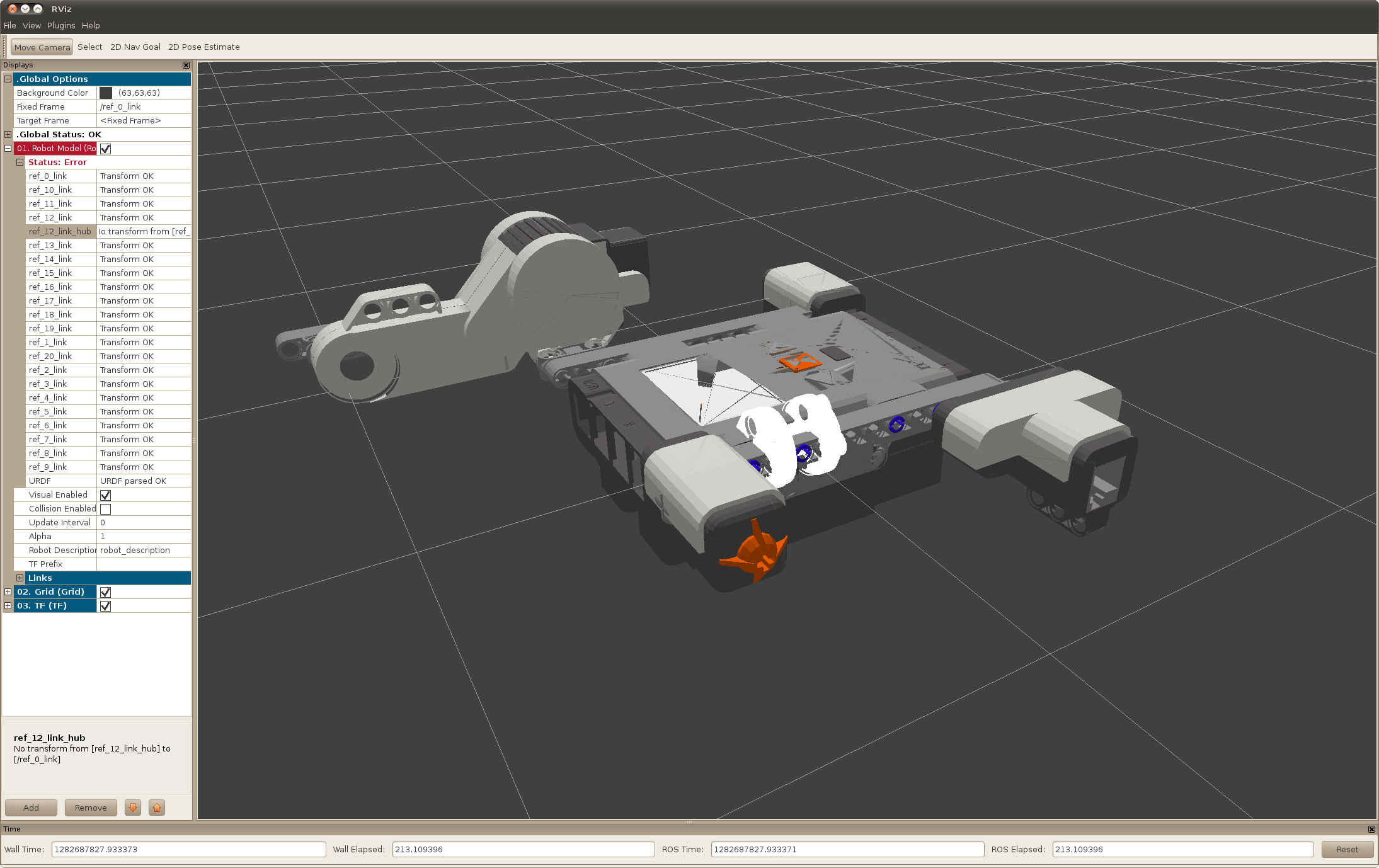
Start by setting your fixed frame to ref_0_link and the Robot Description field to robot_description. You will see something that looks like the image below.

The first thing you should notice is that none of the links have specific names and that the sensors are in funny locations. This is because the names of the links need to be changed to reflect your robot.yaml and all of the sensor frames and origins have been moved and rotated to body centered and x-axis forward by convention.
Renaming Joints
Let's start by renaming our joints to reflect our robot.yaml. Open up our robot.urdf and look for the following comment:
<!--THIS IS THE MOTOR JOINT RENAME AND FIX BY 180 WHEN NEEDED-->
Once you find this comment you need to edit the joint to reflect the robot.yaml. In this case all we need to do is change the joint name.
    <!--THIS IS THE MOTOR JOINT RENAME AND FIX BY 180 WHEN NEEDED-->
    <joint name="l_motor_joint" type="continuous">
      <parent link="ref_12_link"/>
      <child link="ref_12_link_hub"/>
      <origin xyz="0 0 0" rpy="0 0 0" />
      <axis xyz="1 0 0" />
    </joint>
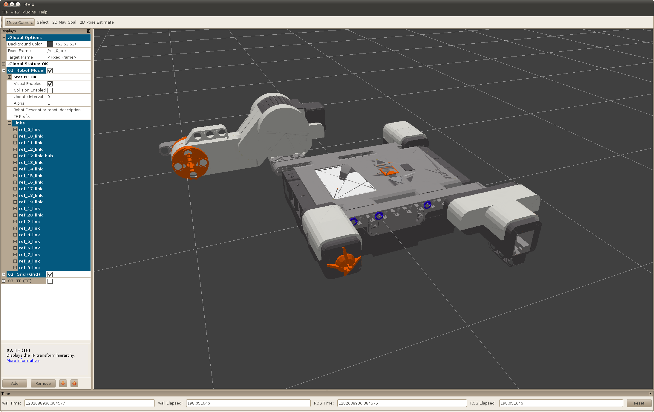
Now relaunch your robot and look at what has now changed. You will now see that the robot model no longer shows an error and the motor hub is rendered in the correct location. This is because there is now a transform being published for the continuous joint in the robot model (l_motor_joint).


