| |
Using NDT Fuser to create an NDT map
Description: This tutorial guides through the sreps of setting up an NDT Fuser node and using it to create an NDT map of the environment. The map can then be saved and used for other tasks, such as localizationKeywords: Mapping, NDT Maps
Tutorial Level: BEGINNER
Next Tutorial: Running NDT-MCL examples
Contents
Getting Started
Depending on if you installed from source or from the pre-built packages, you need to locate the source directories for the ndt_fuser package. As of ROS-indigo, we no longer have a dependency on the MRPT kit, so no additional packages need to be configured. For ROS-kinetic, there is currently no binary release, so please download from the branc port-kinetic at our source github at https://github.com/OrebroUniversity/perception_oru.git
Download the tutorial data
The example launch files located in ndt_fuser/launch are configured to work with several sample data sets available at the MRO lab page. If you want to directly download the data sets follow these steps:
roscd ndt_fuser/data
wget http://aass.oru.se/Research/mro/data/tutorials/mapping.bag
wget http://aass.oru.se/Research/mro/data/tutorials/localization.bag
wget http://aass.oru.se/Research/mro/data/tutorials/3d_laser_short.bag
Note that the last bag file is large (300MB) as it contains raw dta from a Velodyne-32 lidar.
2D laser fuser
The first basic useage of the ndt_fuser node is for creating 2D laser maps of the environment. Although there are many excelent SLAM packages out there, you may need this in case you want to create and NDT map for use in the ndt_mcl localization framework. In order to run the tutorial examples, start up the launch file:
roslaunch ndt_fuser fuser_2dlaser.launch
If everything works, you should see an empty gray window entitled NDTViz appearing. Next, bring either one of the three bag files that you downloaded, for example:
roscd ndt_fuser && rosbag play data/mapping.bag
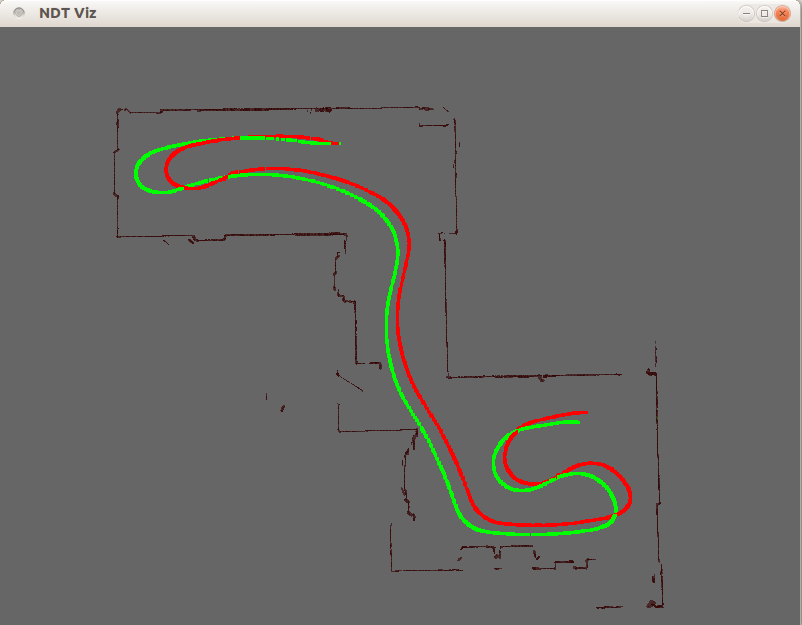
Data from the recorded bag file should then start flowing through the system and the visualization window should look something similar to this:

What you see in this display:
- The odometry track of the vehicle as green points
- The estimated vehicle position as a red track
The currently reconstructed NDT-OM map. The map is represented as a set of confidence ellipsoids, scaled and oriented according to the Gaussian probability function stored in each consistently occupied cell.
- The NDT model of the currently inserted laser scan as green ellipsoids
Note that for performance reasons, the visualization of the map is only updated after a certain number of scans have been inserted. The vehicle position in the visualization on the other hand is updated for each processed pose.
At any point in time, the current NDT map can be saved by calling the service
rosservice call /laser_fuser_2d/save_map "{}"This will save the map in a predefined directory / filename as specified in the launch file. Before proceeding with the 3D ndt maps, let's look in more detail at the parameters in the launch file.
launch file explained
<launch>
  <node pkg="ndt_fuser" type="ndt_fuser" name="laser_fuser_2d" output="screen">
        <param name="laser_topic" value="/laserscan" />
        <param name="matchLaser" value="true" />

        <param name="size_x_meters" value="30" />
        <param name="size_y_meters" value="30" />
        <param name="size_z_meters" value="0.8" />
        <param name="resolution" value="0.4" />
        <param name="laser_variance_z" value="0.02" />

        <param name="sensor_range" value="20." />
        <param name="min_laser_range" value="0.5" />

        <!-- Specific sensor offset parameters for the example file -->
        <param name="sensor_pose_x" value="0.695" />
        <param name="sensor_pose_y" value="-0.01" />
        <param name="sensor_pose_t" value="-0.0069813" />

        <param name="pose_init_x" value="10.727" />
        <param name="pose_init_y" value="2.186" />
        <param name="pose_init_t" value="0.05" />

        <param name="map_directory" value="$(find ndt_fuser)/maps/" />
        <param name="map_name_prefix" value="basement2d" />

        <param name="beHMT" value="false" />
        <param name="useOdometry" value="true" />
        <param name="odometry_topic" value="/vmc_navserver/odom" />
        <param name="visualize" value="true" />
    </node>
</launch>
The ndt_fuser node launched here is configured to work on LaserScan messages (instead of PointCloud2) messages. This, as well as the topic of the laser scan messages are indicated by:
        <param name="laser_topic" value="/laserscan" />
        <param name="matchLaser" value="true" />
The next three lines define the size of the map in meters. Note that these parameters have different semantics when operating in HMT mode. If this is the case, the sizes refer to the central grid map. I.e., the actual size of the map in memory in HMT mode is (size_x*3, size_y*3, size_z). Note that although we are building a 2D map, the basic algorithm behind the scenes is the same. Thus, we need to indicate a size along the z axis. It is recommended to have at least 2 layers of cells along the z axis, as using only one layer has sometimes resulted in strange raytracer behavior. The size of each NDT cell is determined by the resolution parameter.
<param name="resolution" value="0.4" />
The next parameter governs the amount of artificial noise along the z-axis which is added to the projected laser points. This is again necessary, as we are operating in three dimensions. The next two parameters govern the maximum and minimum sensor range when inserting measurements.
        <param name="sensor_range" value="20." />
        <param name="min_laser_range" value="0.5" />
The minimum range only applies to the LaserScan topic at the moment (not the PointCloud2!). The maximum range has slightly different semantics, as it defines the maximum size of the local NDT map used internally for sensor dta representation. The next size parameters define the 2D pose of the laser with respect to the vehicle base frame and the inital position of the vehicle. Full 3D poses can also be defined. In future releases an option to get these values from /tf is envisioned. The directory and base name of the saved maps can be set using:
        <param name="map_directory" value="$(find ndt_fuser)/maps/" />
        <param name="map_name_prefix" value="basement2d" />
You can enable/disable odometry and set the topic name using :
        <param name="useOdometry" value="true" />
        <param name="odometry_topic" value="/vmc_navserver/odom" />
Finally, you can switch on/off the visualization and more importantly the submap indexing (the HMT implementation). Let's now take a look at a 3D case.
3D laser fuser
In order to start the 3D ndt fuser:
roslaunch ndt_fuser fuser_velodyne32.launch
roscd ndt_fuser && rosbag play data/3d_laser_short.bag
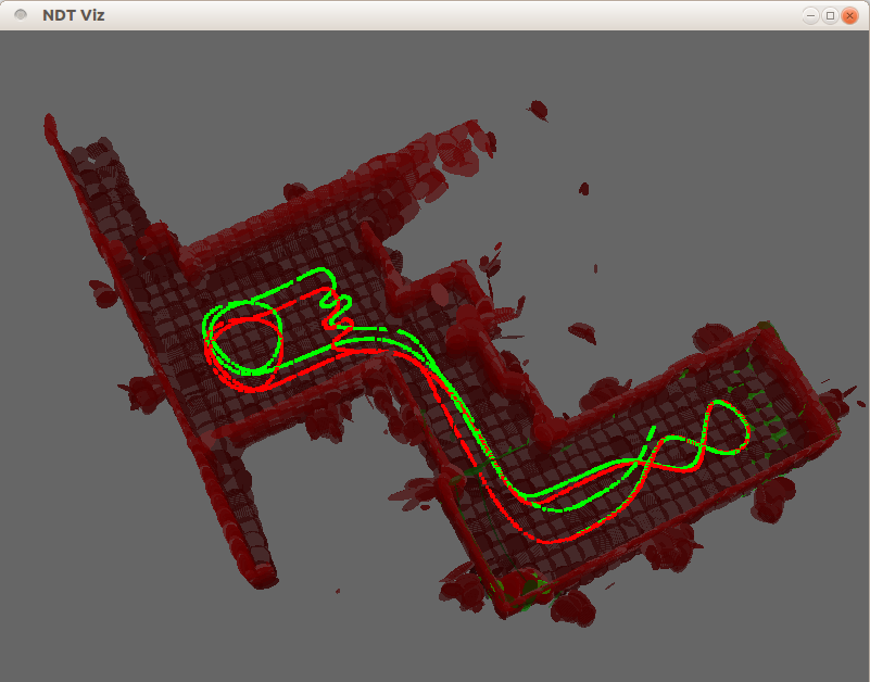
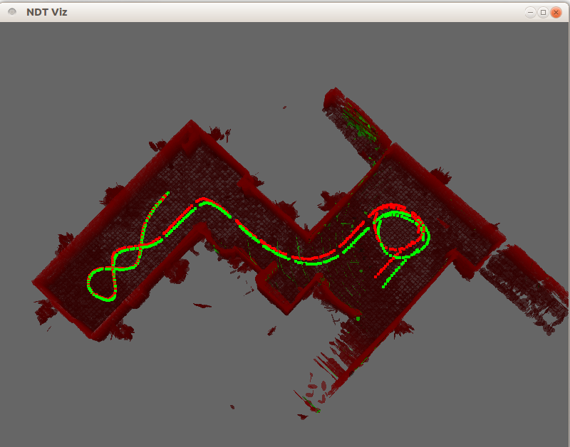
This should start the visualization screen as in the previous example and you should see something which looks like this:

The visualization here follows the same principles as in the previous example, adding a height-coded coloring scheme for the occupied ellipsoids.
launch file explained
The launch file for this example is:
<launch>
    <node pkg="velodyne_pointcloud" type="cloud_node" name="convert_veloscans">
        <param name="calibration" value="$(find ndt_fuser)/launch/velo32.yaml" />
    </node>
    <node pkg="ndt_fuser" type="ndt_fuser" name="fuser_3d" output="screen">
        <param name="points_topic" value="/velodyne_points" />
        <param name="matchLaser" value="false" />
        <param name="size_x_meters" value="40" />
        <param name="size_y_meters" value="40" />
        <param name="size_z_meters" value="4.5" />
        <param name="resolution" value="0.5" />
        <param name="sensor_range" value="30." />

        <!-- Specific sensor offset parameters for the example file -->
        <param name="sensor_pose_x" value="0.3" />
        <param name="sensor_pose_z" value="1.3" />
        <param name="sensor_pose_t" value="-1.62" />

        <param name="pose_init_x" value="10.73" />
        <param name="pose_init_y" value="2.185" />
        <param name="pose_init_t" value="0.05" />

        <param name="map_directory" value="$(find ndt_fuser)/maps/" />
        <param name="map_name_prefix" value="basement3d" />

        <param name="beHMT" value="false" />
        <param name="match2D" value="true" />
        <param name="useOdometry" value="true" />
        <param name="odometry_topic" value="/vmc_navserver/odom" />
        <param name="visualize" value="true" />
    </node>
</launch>
Most of the parameters in the launch file have already been discussed, so we will only outline the new ones. Most notably, we need to set the topic of the point source which in this case is
<param name="points_topic" value="/velodyne_points" />
The other notable parameter we set is
<param name="match2D" value="true" />
This constrains the matcher to work on a plane and speeds up processing times.
modifying parameters and performance issues
Finally, before porting these launch files to your robot, take some time to play with the parameters and check what are good values for yur particular machine. As the processing is done in real time, some configurations can lead to loosing track of the vehicle. Important things to keep in mind are:
- setting the resolution parameter to a lower value will result in more memory-heavy maps. It will also likely slow down the matching and the fusion steps, as well as the visualization. Maps tend to look better (see for example resolution of 0.2 meters bellow), but the distance between processed frames is larger and you may need to replay the bags at a slower rate.

- lower resolution does not always mean better performance. If the cells are too small, data becomes sparser and you are at risk of overfitting.
- If you are mapping larger environments, go for the HMT option.
- Disabling the visualization will generally save on processing time, so for online usage it is recommended. You can see the output transformations on the /tf topic
- In case you are having troubles getting things working, contact the developers, we will be happy to help you.


