Show EOL distros:
Package Summary
Launch a PID control node.
- Maintainer status: developed
- Maintainer: Andy Zelenak <andyz AT utexas DOT edu>
- Author: Andy Zelenak <andyz AT utexas DOT edu>, Paul Bouchier
- License: BSD
- Source: git https://bitbucket.org/AndyZe/pid.git (branch: master)
Package Summary
Launch a PID control node.
- Maintainer status: maintained
- Maintainer: Andy Zelenak <andyz AT utexas DOT edu>
- Author: Andy Zelenak <andyz AT utexas DOT edu>, Paul Bouchier
- License: BSD
- Source: git https://bitbucket.org/AndyZe/pid.git (branch: master)
Package Summary
Launch a PID control node.
- Maintainer status: maintained
- Maintainer: Andy Zelenak <andyz AT utexas DOT edu>
- Author: Andy Zelenak <andyz AT utexas DOT edu>, Paul Bouchier
- License: BSD
- Source: git https://bitbucket.org/AndyZe/pid.git (branch: master)
Package Summary
Launch a PID control node.
- Maintainer status: maintained
- Maintainer: Andy Zelenak <andyz AT utexas DOT edu>
- Author: Andy Zelenak <andyz AT utexas DOT edu>, Paul Bouchier
- License: BSD
- Source: git https://bitbucket.org/AndyZe/pid.git (branch: master)
Package Summary
Launch a PID control node.
- Maintainer status: maintained
- Maintainer: Andy Zelenak <andyz AT utexas DOT edu>
- Author: Andy Zelenak <andyz AT utexas DOT edu>, Paul Bouchier
- License: BSD
- Source: git https://bitbucket.org/AndyZe/pid.git (branch: master)
Package Summary
Launch a PID control node.
- Maintainer status: maintained
- Maintainer: Andy Zelenak <andyz AT utexas DOT edu>
- Author: Andy Zelenak <andyz AT utexas DOT edu>, Paul Bouchier
- License: BSD
- Source: git https://bitbucket.org/AndyZe/pid.git (branch: master)
Contents
Overview
The PID controller package is an implementation of a Proportional-Integral-Derivative controller - it is intended for use where you have a straightforward control problem that you just need to throw a PID loop at. It has one purpose and focuses on doing it well. It has numerous features that ease the task of adding a controller and tuning the control loop. Several examples are provided.
This wiki page uses several terms from control system theory:
- Setpoint: the desired value of a controlled process, e.g. arm position, motor speed, etc.
- Plant state: the actual value of the controlled process. Plant is the name for the process and its state is the property being controlled, e.g. arm position, motor speed, etc.
- Control effort: the amount of force applied by the controller to the controlled process to try to make the plant state equal the setpoint. Control effort may be varied by changing e.g. voltage, duty-cycle, etc.
Features
- Easy to interface to: uses std_msgs/Float64 for setpoint, plant state, and control effort
- Dynamic reconfiguration of Kp, Ki and Kd eases on-the-fly tuning
- Low-pass filter in the error derivative with a parameterized cut-off frequency provides smoother derivative term.
- ROS node-private parameters configure all controller parameters
- Support for multiple controllers
- Support for faster-than-wallclock simulation
- Auto/Manual modes
Simulations of 1st & 2nd order plants allow evaluation of controller features
- A Ziegler-Nichols autotuner
- Support for discontinuous angle measurements
Installing the package
You can install the pid package from binaries or build from source. If you install from binaries, the example files discussed below will be in /opt/ros/<release>/share/pid
Binary Installation
Replace "indigo" with your release in the command below.
$ sudo apt-get install ros-indigo-pid
Install and Build from source
$ cd catkin_ws/src
$ git clone https://bitbucket.org/AndyZe/pid.git
$ cd ..
$ catkin_make
Example: Run servo_sim.launch
Several launch files are provided in the pid/launch directory which launch simulations that showcase controller capabilities. Servo_sim.launch is one such in which the pid controller controls a second-order plant that simulates a servo controlling the position of a load. The control loop runs at 100 Hz.
Roslaunch pid servo_sim.launch, and several windows will open.
$ roslaunch pid servo_sim.launch
An rqt_plot window opens displaying controller inputs and outputs. Click the pan/zoom button and right-click and drag left to zoom out until you see the desired degree of detail in the plot.
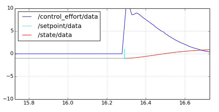
- /setpoint/data is a plot of the std_msgs/Float64 messages which tell the PID controller the desired value the servo should be controlled to. A node in this example is changing the setpoint between 1.0 and -1.0 every 5 seconds.
- /state/data is a plot of the std_msgs/Float64 messages which are input to the PID controller from the controlled system; in this case a simulation of a servo.
- /control_effort/data is a plot of the std_msgs/Float64 messages which are output from the PID controller and which apply correcting force to the controlled system; in this case, voltage to the simulated servo.
/setpoint, /state, and /control effort are the default topic names that the PID controller subscribes to, and publishes on. They can be changed so as to support multiple PID controller nodes using standard ROS techniques like remapping, or alternatively with parameters.
Run "rqt_graph". A window showing the nodes in this simulation opens.
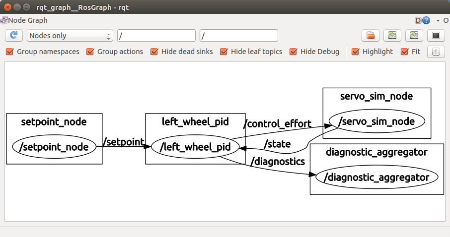
The setpoint_node publishes its time-varying setpoint to the PID controller running in the /left_wheel_pid node, which applies corrections via the /control_effort topic to the servo_sim_node. The servo_sim_node publishes the current value of the simulated servo position to the /state topic, which the PID controller subscribes to and bases its control_effort on.
Dynamically Reconfigure PID Gains
Servo_sim.launch also opens an rqt_reconfigure window:
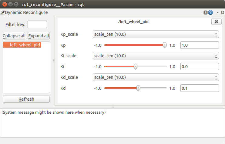
Click on the "left_wheel_pid" entry to display the controls that let you dynamically reconfigure the Kp, Ki and Kd parameters: the PID proportional, integral and derivative contributions to /control_effort. Each parameter has a dropdown scale that lets you select a power of 10 range of the slider, and a slider that lets you set the parameter between -1.0 and +1.0 times the scale. E.g. if you set Kp_scale drop-down to scale_10, and the Kp slider to 0.5, the Kp parameter used by the controller will be 5.
Try dragging the Kd slider to 0 while watching the rqt_plot display. You will see the /control_effort value saturate at the parameterized limit of 10 as well as some overshoot on /state that represents servo position overshoot.
Adjust other parameters and observe their effect. One technique for tuning a PID loop is to adjust Kp as high as you can without inducing wild oscillation, then increase Kd to remove overshoot, then adjust Ki to remove any residual offset after the loop has settled. You should check the tuning with the expected range of loads on the controlled device - the loop may be stable with some loads and unstable with others. Your goal is to get the loop to settle as quickly as possible with as little overshoot as possible.
The idea of dynamic reconfigure for Kp, Ki and Kd is that you get your robot actuator to repeatedly perform a movement, and use dynamic_reconfigure to experimentally find good values for Kp, Ki and Kd. Once you've found values that work well, you should set those parameters in the launch-file node entry that launches that controller.
Autotune
While servo_sim.launch is running, you can launch a Ziegler-Nichols autotuner. It calculates decent values of Kp, Ki, and Kd by cycling through a range of Kp values and recording oscillations. I wouldn't use this on hardware! The ZN method aims for a fast response time and usually results in significant overshoot. To run it:
$ rosrun pid autotune
If you want to customize the autotuner for your application, these are the values in autotune.cpp that need changing:
- nameSpc = "/left_wheel_pid/" (may be blank if you are only running 1 PID controller)
- numLoops (adjust how long the autotuner observes the plant for each Kp it tries)
- Kp_min, Kp_max, Kp_step (define the range of Kp values to be searched)
Controller Node
The controller node is the main node in the package. It implements the PID algorithm and applies control effort to try and make plant state equal setpoint.
Topics
The PID controller subscribes and publishes to the following topic names. The setpoint, state and control_effort topic names are defaults and can be changed in the standard way with ROS techniques like remapping and namespaces, or in a pid-package-specific way using controller parameters.
- setpoint: The controller subscribes to this topic and reads std_msgs/Float64 messages. The message data element must contain the desired value of the state measurement of the controlled process.
- state: The controller subscribes to this topic and reads std_msgs/Float64 messages. The message data element must contain the current value of the controlled plant property. The controller publishes std_msgs/Float64 messages on the control_effort topic each time it receives a message on the state topic. Thus the rate at which the plant publishes state governs the control-loop rate - the plant should publish state at the desired loop rate.
- control_effort: The control_effort message data element contains the control effort to be applied to the process to drive state/data to equal setpoint/data.
- pid_enable: controller subscribes to this topic and reads std_msgs/Bool messages. The data element disables controller if false: controller stops publishing control_effort and holds the error integral at 0. A true value re-enables the controller. The name of this topic can be changed in the launch file if you have multiple PID controllers.
- pid_debug: publishes an array that can be useful for debugging or tuning. The array contains five numbers: plant state, control effort, Proportional contribution, Integral contribution, Derivative contribution
Parameters
The following node-private parameters are read at node startup:
Kp, Ki, Kd: The values to be used for proportional, integral, and derivative gains. These values are used by the node unless overridden by dynamic reconfiguration. Kp, Ki and Kd should all have the same sign! Use all positive values for direct-acting loops (where an increase in control effort produces an increase in state). Use all negative values for reverse-acting loops (where an increase in control effort produces a decrease in state). Defaults are 1.0, 0, and 0 for Kp, Ki and Kd.
- upper_limit, lower_limit: the maximum and minimum limits for control_effort. Defaults are 1000, -1000.
- windup_limit: The maximum limit for error integral. Default is 1000.
- cutoff_frequency: The cutoff frequency of the low-pass filter on the derivative term (in Hz). Default is 1/4 of the sampling rate.
- topic_from_controller: The topic name that control_effort will be published to. The plant must subscribe to this topic. Default is "control_effort".
- topic_from_plant: The topic name that controller subscribes to for updates from the plant. Default is "state"
- setpoint_topic: The topic name that controller subscribes to for updates to the desired value of plant state. Default is "setpoint".
- node_name: The name given to the node being launched. Default if not otherwise specified is "pid_node".
- max_loop_frequency, min_loop_frequency: The maximum and minimum expected frequency at which the plant issues state messages and the control loop runs and generates control_effort. The frequency is controlled by the rate at which the plant publishes state. This can be useful to detect that a node or sensor has failed. Defaults are arbitrary: minimum 1 Hz, maximum 1000 Hz.
- pid_enable_topic: The name of the topic where a Boolean is published to turn on/off the PID controller. This is modifiable in case there are multiple PID controllers. The default is "pid_enable".
- angle_error: Set this boolean to "true" if the state is a potentially discontinuous angular error measurement. It will maintain the angular error between -pi:pi, or -180:180. The default is "false."
- angle_wrap: Related to angle_error. Helps to maintain an angular error (in radians) between -pi:pi. Could be set to 2.0*180.0 for degree measurements. The defualt is "2.0*3.14159."
- setpoint_timeout: Setpoint timeout parameter to determine how long to keep publishing control_effort messages after last setpoint message. -1 indicates publish indefinitely, and positive number sets the timeout in seconds
How to use Controller Features
These sections give examples of how to use various pid controller features.
Configuring with node-private parameters
The pid controller makes heavy use of parameters to set its operating characteristics. Use the launch-file node-private parameter syntax documented here to set parameters from a launch file, or the rosrun parameter syntax documented here to set parameters from the command line.
The following snippet from a launch file shows how to launch the node and set its parameters from a launch file.
    <node name="left_wheel_pid" pkg="pid" type="controller" >
      <param name="Kp" value="5.0" />
      <param name="Ki" value="0.0" />
      <param name="Kd" value="0.1" />
      <param name="upper_limit" value="10" />
      <param name="lower_limit" value="-10" />
      <param name="windup_limit" value="10" />
      <param name="max_loop_frequency" value="100.0" />
      <param name="min_loop_frequency" value="100.0" />
    </node>
Dynamic Reconfiguration
rosrun rqt_reconfigure rqt_reconfigure
The pid nodes will be displayed in the left pane. Select any of the nodes and its Kp, Ki, and Kd reconfiguration controls will be displayed in the main pane. Tune each controller as needed.
Support for multiple controllers (with example)
Any real robot is likely to have multiple PID loops, and likely instantiates multiple controller nodes. The problems to deal with are:
- Each controller needs to subscribe to the plant state topic from its assigned plant
- Each controller needs to publish on a different control_effort topic so as to control their assigned plant.
- The multiple controllers may subscribe to different, or to the same setpoint topic
ROS provides two ways of supporting this need to connect controller nodes to different topic names, and the pid controller node provides a third:
Push each controller node into its own namespace (perhaps together with its plant). The controller topic names are then prefixed with the namespace. The book "A Gentle Introduction to ROS" by Jason O'Kane, chapter 6 section 6.3 describes the technique and gives examples.
Remap topic names, such that the topic name each controller publishes or subscribes to is remapped to something appropriate. See "A Gentle Introduction to ROS" chapter 6 section 6.4 for an explanation with examples.
- Tell the PID controller which topics to publish/subscribe to using parameters. This technique is pid-controller specific - see the parameters section.
Example
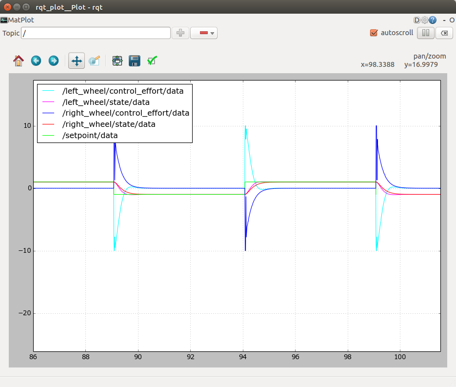
Roslaunch the pid differential_drive_sim.launch example. The launch file starts two controller/plant pairs, simulating the left and right drive motors and controllers of a differential drive robot. As is sometimes the case, one wheel needs a positive voltage to drive the robot forward, and the other needs a negative voltage (to turn the wheel the other way) to drive the robot forward.
The figure below shows the node graph.
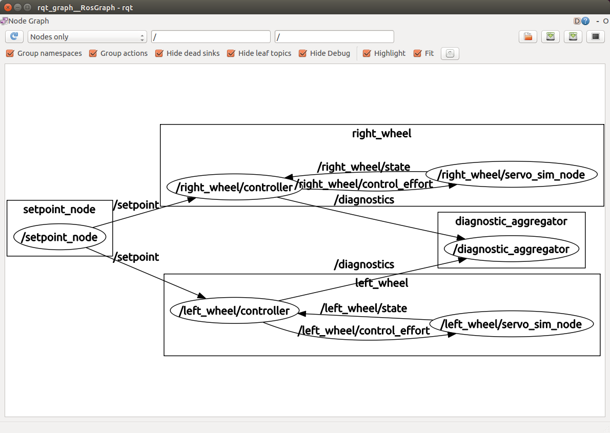
Each controller and its associated plant simulation has been pushed down into a separate namespace, identified as "left_wheel" and "right_wheel". See the "ns=left/right_wheel" property in the node elements. Since the default topic names used by controller and plant are relative names, ROS has prepended their namespaces to the topic name paths, and thus each controller node is connected only to the correct plant node.
Both controllers should listen to the same /setpoint topic in this example. The nodes' setpoint topic names are remapped to the top-level setpoint topic published by the setpoint node.
The launchfile snippet shown below instantiates the two nodes and their plants, connecting the topics properly using the push-down and the remapping techniques. The "ns" property pushes the controller down into a namespace. The remap element remaps the node's /namespace/setpoint topic to the global /setpoint topic.
    <node name="controller" pkg="pid" type="controller" ns="left_wheel" output="screen" >
      <param name="node_name" value="left_wheel_pid" />
      <param name="Kp" value="5.0" />
      <param name="Ki" value="0.0" />
      <param name="Kd" value="0.1" />
      <param name="upper_limit" value="10" />
      <param name="lower_limit" value="-10" />
      <param name="windup_limit" value="10" />
      <param name="max_loop_frequency" value="100.0" />
      <param name="min_loop_frequency" value="100.0" />
      <remap from="setpoint" to="/setpoint" />
     </node>

    <node name="servo_sim_node" pkg="pid" type="plant_sim" ns="left_wheel" output="screen" >
      <param name="plant_order" value="2" />
    </node>

    <node name="controller" pkg="pid" type="controller" ns="right_wheel" output="screen" >
      <param name="node_name" value="right_wheel_pid" />
      <param name="Kp" value="-4.0" />
      <param name="Ki" value="-0.0" />
      <param name="Kd" value="-0.3" />
      <param name="upper_limit" value="10" />
      <param name="lower_limit" value="-10" />
      <param name="windup_limit" value="10" />
      <param name="max_loop_frequency" value="100.0" />
      <param name="min_loop_frequency" value="100.0" />
      <remap from="setpoint" to="/setpoint" />
     </node>

    <node name="servo_sim_node" pkg="pid" type="plant_sim" ns="right_wheel" output="screen" >
      <param name="plant_order" value="2" />
      <param name="reverse_acting" value="true" />
    </node>
A plot of the resulting two-controller simulation is shown below. Note: the Kp, Ki, and Kd parameters are intentionally a little different for each simulated wheel to distinguish the plots.
Reverse acting support
The launch file snippet above has Kp, Ki, Kd all positive in the left_wheel controller, and all negative in the right_wheel controller. This causes the right wheel controller to emit control_effort that's opposite polarity to the error.
Auto/Manual
Manual control means the pid controller stops publishing control_effort messages, and the error integral is zero. Automatic control means the controller applies control_effort to reduce the difference between setpoint and state. The controller starts in Auto mode. Send the controller an std_msgs/Bool message with data set false to put it into Manual mode. A message with data set true puts it back into Auto mode. The controller listens on the pid_enable topic. Remap it as needed to put individual controllers or groups of them into Manual or Auto mode.
This feature is useful if you want to suspend a PID controller, maybe swapping in a different controller or taking over manual control.
Faster-than-wallclock simulation
The controller node (and other nodes in the pid package) are designed to support running simulations faster than wallclock using the standard ROS support for this. By setting the "use_sim_time" parameter true, roscpp listens for time to advance as indicated by new time values published on the /clock topic.
The controller waits for time to become non-zero before beginning operation. After that, its calls to time primitives like ros::Rate::sleep() will act based on published time, not system time.
Example
Roslaunch pid sim_time.launch - it runs a control loop simulation faster than wallclock. An rqt_plot window opens showing the simulated temperature control loop in operation. Look at the time scale - it is running at 4X wallclock time.
This is accomplished by the following launchfile statements:
    <param name="use_sim_time" value="true" />

        <node name="sim_time" pkg="pid" type="sim_time" output="screen" >
      <param name="sim_speedup" value="4" />
    </node>
Setting the global parameter "use_sim_time" true causes roscpp and rospy (which all the nodes use for ros time services like Duration, ros::Time::now(), and ros::Rate::sleep()) to behave as if time advances according to time markers published on the /clock topic, instead of on wallclock time.
The sim_time node publishes time markers on the /clock topic in 10ms increments, at a rate set by the sim_speedup parameter. This launchfile asks for a sim_speedup of 4, so it will publish a 10ms time increment every 2.5ms of wallclock time. Note: it could also run simulation time slower than wallclock.
Other nodes
The pid package contains several other nodes which support the demo launch files:
- setpoint_node. Publishes a value on setpoint that alternates between +1 and -1 every 5 seconds
- plant_node. Subscribes to control_effort and publishes on state. Simulates a first or second-order plant (selectable). Parameters:
- plant_order: 1 or 2 selects first or second order plant. Default: 1
- reverse_acting: true to cause an increase in control effort to produce a decrease in state. Default: false
- sim_time node. Publishes 10ms increments of time on the /clock topic. Parameter:
- sim_speedup: Divider for the wallclock time delay between emitting 10ms time increments. Default: 1
Filtering
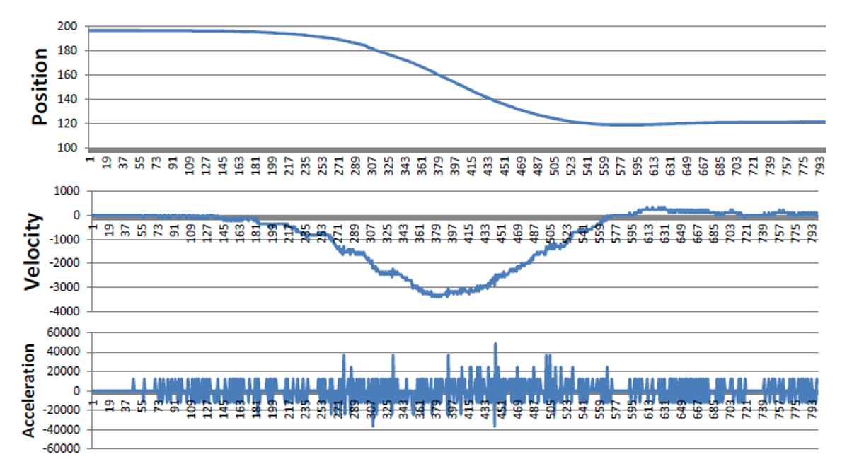
Filtering is important to eliminate noise in digital signals, especially when differentiating. The following screenshot (Nicholas Paine, 2012) shows a noisy second derivative when the signal is unfiltered. The default cutoff frequency (1/4 of the sampling rate) should be fine for most applications. If you prefer not to filter the signal anyway, just set a very high cutoff frequency (like 10,000).
Known Issues
If you're seeing high CPU usage, it's probably due to rqt_plot. You can comment it in the launch files. The PID controller itself (no graphics) typically runs at <10% CPU usage.
Submit Issues Here
Submit issues here: bitbucket issues


