| |
How to set up CAN connection to Pilz Manipulator Module
Description: Learn how to set up the Pilz Manipulator Module PRBT and move the robot for the first time.Keywords: Industrial, PRBT, CAN
Tutorial Level: ADVANCED
Note: Please be aware that the Pilz command planner has moved to MoveIt and http://wiki.ros.org/pilz_robots and http://wiki.ros.org/pilz_industrial_motion are unmaintained. These tutorials are outdated and might or might not work dependent on the ROS distro.
Contents
WARNING
INDUSTRIAL ROBOTS ARE VERY DANGEROUS AND CAN SERIOUSLY INJURE OR KILL. THE PILZ SOFTWARE IS PROVIDED AS-IS AND WITH NO WARRANTY (FOR MORE DETAILS SEE LICENSE). WHEN OPERATING AN INDUSTRIAL ROBOT UNDER PILZ CONTROL, MAKE SURE THAT NO ONE IS WITHIN THE ROBOT WORKSPACE AND THE E-STOP IS UNDER OPERATOR CONTROL.
System or plant integrators only
This tutorial is solely intended for system or plant integrators only. The system or plant integrator is responsible for taking into account the requirements from the respective current standard e.g. EN ISO 10218-2 or taking equivalent measures.
Introduction
This tutorial is solely intended for system or plant integrators interested in setting up the Pilz Manipulator Module PRBT. The tutorial describes a minimal setup for controlling the robot with ROS.
Prerequisites
In order to complete this tutorial, you need the following:
The PRBT manipulator operation manual. This tutorial does not replace the operation manual! Read it carefully first!
Completed steps 1-4 of tutorial Model your first application using the Pilz Manipulator Module PRBT
A CAN adapter to communicate from your PC via CAN to the robot. If you are missing a CAN interface, you can try PEAK PCAN-USB which was tested with the robot.
A termination resistor to the CAN data line at your end. If your interface does not have one included, you need a separate one (e.g. this or this.)
- A 24V power supply.
Cable setup
- Don't forget to connect the functional earth connection at pin 5 from X1 (power) and the functional earth connection at the base of the robot with the earth potential with low impedance.
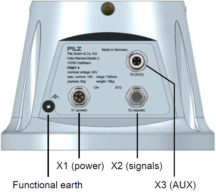
In order to move the robot, the PRBT manipulator needs to be connected to an appropriate power supply (X1), safety controller and to ROS via CANopen (X2). All connections can be found at the base of the robot, as shown in the picture above.
Connect the signals STO_A and STO_B according to chapter 4.10 "STO inputs of the robot arm" of the PRBT manipulator operation manual.
The exact pin specification for each connector is described in chapter 9 of the PRBT manipulator operation manual.
For this minimal setup, you can ignore X3 (AUX).
Connect CAN to the PC
- The baud rate of your CAN device needs to be set to 1 Mbit/s.
- Please, don't forget to terminate your CAN, to avoid disturbances/errors.
Setup can interface
To set up the can interface append the following to the file /etc/network/interfaces
auto can0
iface can0 can static
        bitrate 1000000
after this connect your CAN Adapter and reboot.
After the reboot open a terminal and run
ifconfig -a
and look for a can0 entry which should appear.
Start robot driver and moveit
To tell the ROS system which programs (nodes) it should start, it needs a launch file. Assuming you already created a catkin package named pilz_tutorial (see Tutorial Model your first application using the Pilz Manipulator Module PRBT), continue now with creating the launch file:
cd ~/catkin_ws/src/pilz_tutorial
mkdir launch
gedit launch/my_start_up_application.launch
with the following content:
   1 <?xml version="1.0"?>
   2 <launch>
   3
   4   <include file="$(find prbt_support)/launch/robot.launch">
   5
   6     <!--
   7     Only set this value to false if you know exactly what you are doing.
   8     Never use this setting in production. Always make sure you apply to
   9     your local safety regulations.
  10     -->
  11     <arg name="iso10218_support" value="false"/>
  12
  13   </include>
  14
  15   <include file="$(find prbt_moveit_config)/launch/planning_context.launch"/>
  16
  17   <!-- Bringup the planner including environment collision checking -->
  18   <include file="$(find prbt_moveit_config)/launch/move_group.launch"/>
  19
  20   <!-- Start RViz visualization. Comment this on headless hardware, if you just want to run the driver -->
  21   <include file="$(find prbt_moveit_config)/launch/moveit_rviz.launch">
  22      <arg name="rviz_config" value="$(find prbt_moveit_config)/launch/moveit.rviz" />
  23   </include>
  24
  25 </launch>
(Note: by including robot.launch without sim=true, we indicate that we want to control a real robot)
Execute the launch file from a terminal to startup the application:
roslaunch pilz_tutorial my_start_up_application.launch
After this the visualization tool RVIZ should open up on your screen. 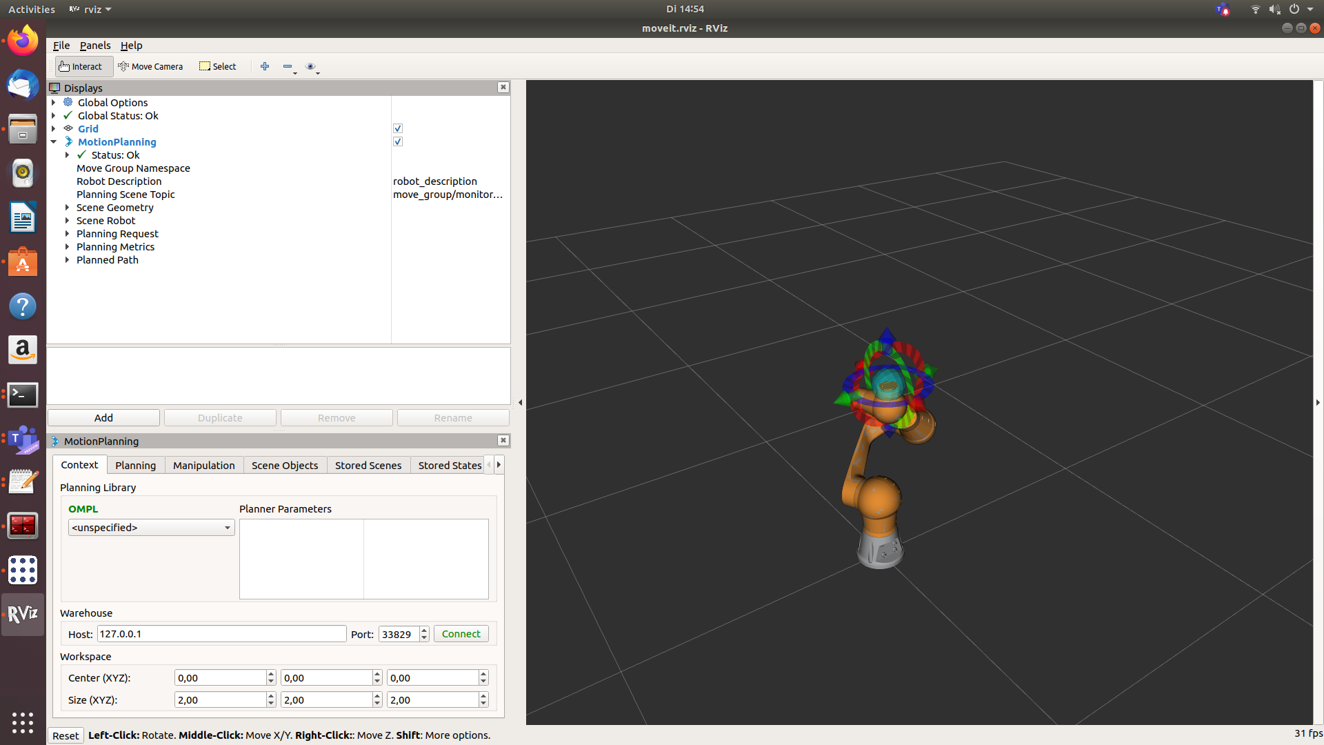
If the robot was disabled by releasing the STO signal and if the STO signal is enabled again, the recover service has to be called. This can be achieved with:
rosservice call /prbt/driver/recover
(Note that in the final setup, this will be done automatically, using the modbus connection to the safety controller)
Control robot with RViz
A detailed description of how to control the robot can be found here:
Move your robot with the pilz_command_planner
Here follows a brief description:

The robot should be shown in RViz without any virtual environment. Activate "MotionPlanning".
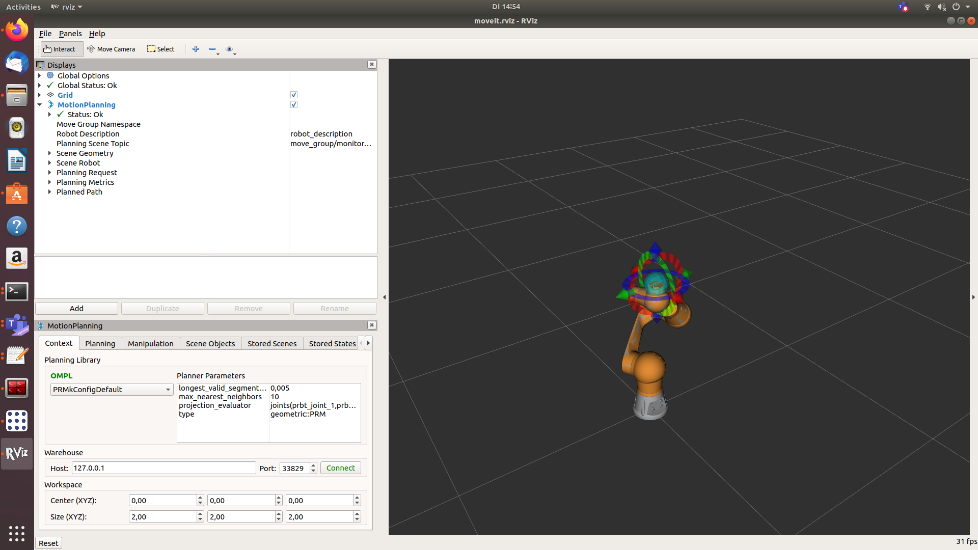
Change OMPL setting like in the picture above.
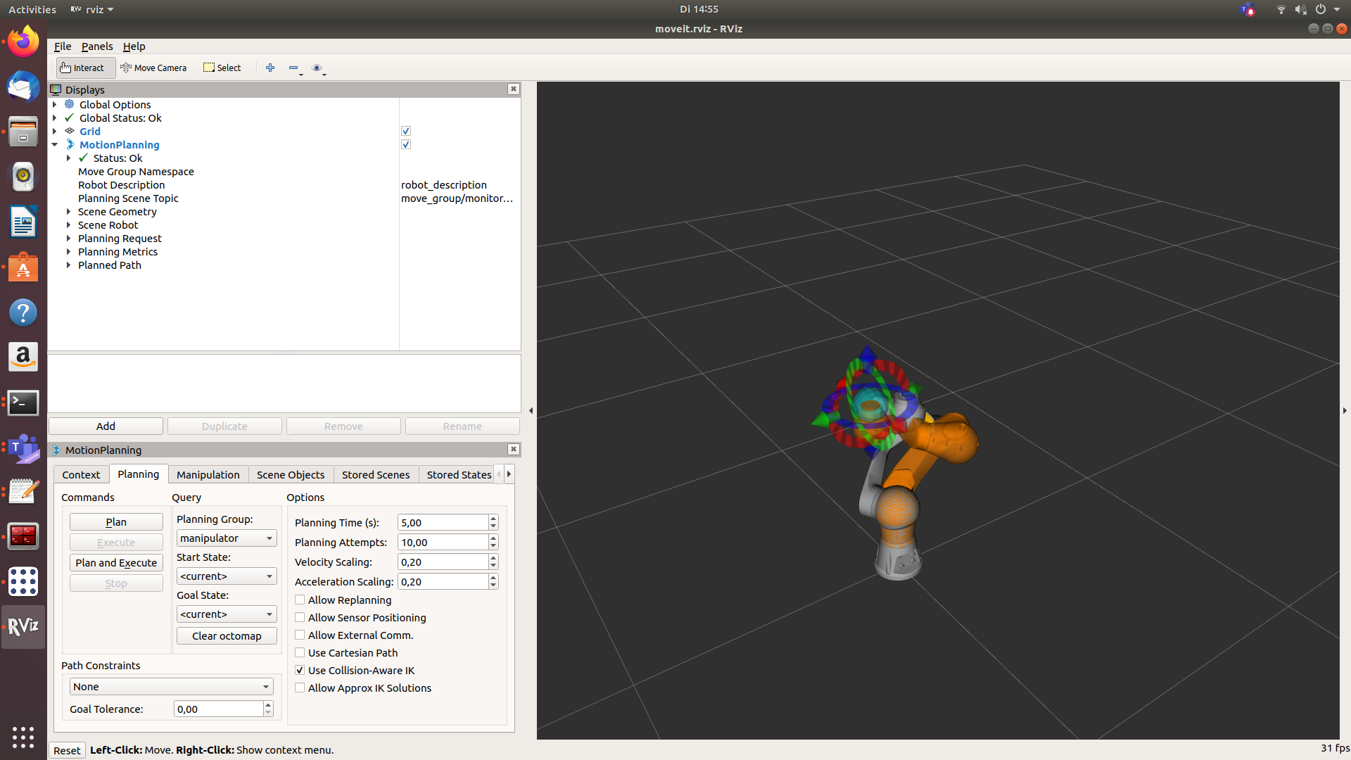
Activate the planning tab. Move the robot by dragging the blue sphere to your desired position. If you want to move the flange in a certain Cartesian direction, use the arrows.
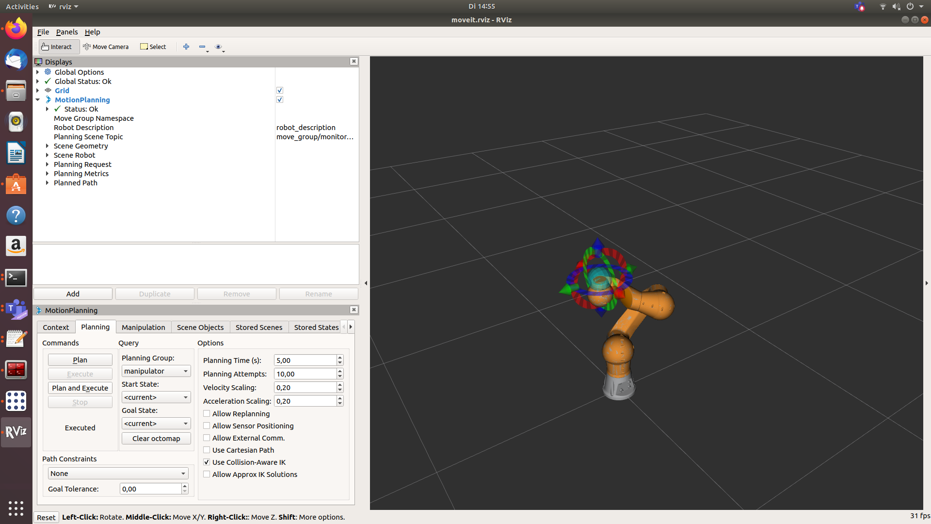
Choose the tabulator "Planning" press button "Plan and Execute". The robot should move to the desired position.
Troubleshooting
CAN not connected
If the CAN interface is not present the following error message will occur while executing the launch file:
[ERROR] [1588080410.611337614]: CAN not ready
[ERROR] [1588080410.611411000]: Initializing failed: CAN init failed; CAN is not ready
Solution: Connect the CAN interface to your computer.
If the robot is turned off or the CAN cable is disconnected, has a shortcut or is not terminated the following error message will occur while executing the launch file:
[ERROR] [1588080681.405137684]: Initializing failed: could not reset node '3' [robot_init-6] process has finished cleanly ...
Solution: Switch on the robot. Connect/repair/terminate the CAN cable.
No STO-Signal/acknowledge at start
If no STO-Signal/acknowledge is set the following messages will occur while executing the launch file:
[1588080828.851057075]: EMCY received: 83#0000000000000000 [ERROR]
[1588080828.854787645]: EMCY received: 84#0000000000000000 [ERROR]
[1588080828.858364732]: EMCY received: 85#0000000000000000 [ERROR]
[1588080828.862662221]: EMCY received: 86#0000000000000000 [ERROR]
[1588080828.866282736]: EMCY received: 87#0000000000000000 [ERROR]
[1588080828.869318528]: EMCY received: 88#0000000000000000 [ INFO]
...
[ERROR] [1588080829.106695064]: Node has emergency error; Node has emergency error; Node has emergency error; Node has emergency error; Node has emergency error; Node has emergency error
Solution: Check the STO-switch and the STO-cable.
Connect the STO-Signal according to chapter 4.10 "STO inputs of the robot arm" of the PRBT manipulator operation manual.
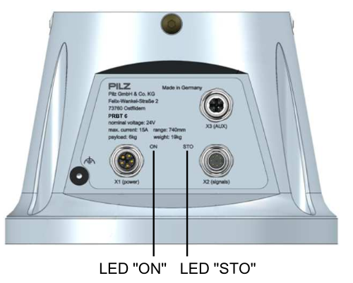
Activate the STO-switch. You can check if the robot was enabled successfully by checking the color LED "STO":
