| Note: This tutorial assumes that you have completed the previous tutorials: Arduino IDE Setup. |
| |
IR Ranger Tutorial
Description: Using an IR Ranger with rosserial and an ArduinoTutorial Level: BEGINNER
Next Tutorial: SRF08 Ultrasonic Range Finder
Show EOL distros:
rosserial allows you to easily integrate Arduino-based hardware with ROS. This tutorial will explain how to use a sharp IR ranger with an Arduino.
You will need an Arduino which you can purchase here for example. Additionally, you will need a Sharp IR Ranger, Model# GP2D120XJ00F, and a way to connect your IR Ranger to your Arduino such as a breadboard or protoboard. If you have a different model IR Ranger, you'll need to modify the code based on your model. This is a helpful Arudino library for some other popular models.
Hardware Setup
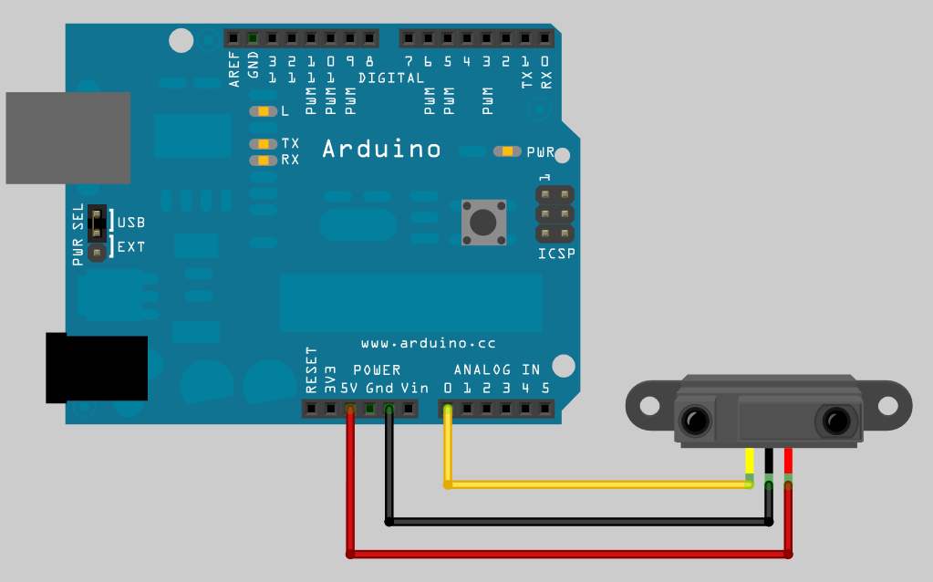
To get started, connect your ranger to your Arduino as shown below. Make sure to connect the signal pin of the ranger to analog input 0.
Software Setup
The Code
Next, open up your Arduino IDE and copy in the code below. The code can also be found in the rosserial_arduino_demos package under 'sketches\IrRanger'.
   1 /*
   2  * rosserial IR Ranger Example
   3  *
   4  * This example is calibrated for the Sharp GP2D120XJ00F.
   5  */
   6
   7 #include <ros.h>
   8 #include <ros/time.h>
   9 #include <sensor_msgs/Range.h>
  10
  11 ros::NodeHandle  nh;
  12 sensor_msgs::Range range_msg;
  13 ros::Publisher pub_range( "range_data", &range_msg);
  14
  15 const int analog_pin = 0;
  16 unsigned long range_timer;
  17
  18 /*
  19  * getRange() - samples the analog input from the ranger
  20  * and converts it into meters.
  21  *
  22  * NOTE: This function is only applicable to the GP2D120XJ00F !!
  23  * Using this function with other Rangers will provide incorrect readings.
  24  */
  25 float getRange(int pin_num){
  26     int sample;
  27     // Get data
  28     sample = analogRead(pin_num)/4;
  29     // if the ADC reading is too low,
  30     //   then we are really far away from anything
  31     if(sample < 10)
  32         return 254;     // max range
  33     // Magic numbers to get cm
  34     sample= 1309/(sample-3);
  35     return (sample - 1)/100; //convert to meters
  36 }
  37
  38 char frameid[] = "/ir_ranger";
  39
  40 void setup()
  41 {
  42   nh.initNode();
  43   nh.advertise(pub_range);
  44
  45   range_msg.radiation_type = sensor_msgs::Range::INFRARED;
  46   range_msg.header.frame_id =  frameid;
  47   range_msg.field_of_view = 0.01;
  48   range_msg.min_range = 0.03;  // For GP2D120XJ00F only. Adjust for other IR rangers
  49   range_msg.max_range = 0.4;   // For GP2D120XJ00F only. Adjust for other IR rangers
  50 }
  51
  52 void loop()
  53 {
  54   // publish the range value every 50 milliseconds
  55   //   since it takes that long for the sensor to stabilize
  56   if ( (millis()-range_timer) > 50){
  57     range_msg.range = getRange(analog_pin);
  58     range_msg.header.stamp = nh.now();
  59     pub_range.publish(&range_msg);
  60     range_timer =  millis();
  61   }
  62   nh.spinOnce();
  63 }
The Code Explained
Now let's break down the code.
As always, the code begins by including the appropriate message headers and ros.h from the rosserial library and then instantiating the publisher.
  15 const int analog_pin = 0;
  16 unsigned long range_timer;
  17
  18 /*
  19  * getRange() - samples the analog input from the ranger
  20  * and converts it into meters.
  21  *
  22  * NOTE: This function is only applicable to the GP2D120XJ00F !!
  23  * Using this function with other Rangers will provide incorrect readings.
  24  */
  25 float getRange(int pin_num){
  26     int sample;
  27     // Get data
  28     sample = analogRead(pin_num)/4;
  29     // if the ADC reading is too low,
  30     //   then we are really far away from anything
  31     if(sample < 10)
  32         return 254;     // max range
  33     // Magic numbers to get cm
  34     sample= 1309/(sample-3);
We then define the analog_pin that the ranger is attached to, creates a timer variable, and defines a function that converts the analog signal to a corresponding distance reading in meters.
Here, the code creates a global variable for the sensors frame id string. It is important to make this string global so it will be alive for as long as the message will be in use.
  37 char frameid[] = "/ir_ranger";
  38
  39 void setup()
  40 {
  41   nh.initNode();
  42   nh.advertise(pub_range);
  43
  44   range_msg.radiation_type = sensor_msgs::Range::INFRARED;
  45   range_msg.header.frame_id =  frameid;
  46   range_msg.field_of_view = 0.01;
  47   range_msg.min_range = 0.03;  // For GP2D120XJ00F only. Adjust for other IR rangers
  48   range_msg.max_range = 0.4;   // For GP2D120XJ00F only. Adjust for other IR rangers
  49
In the Arduino's setup function, the code initializes the node handle and then fills in the descriptor fields for range_msg. This particular IR Ranger reads between 3cm and 40cm.
Note: Many IR libraries report in centimeters by default. You may need to convert their readings to meters if you're using a different Ranger or IR helper library.
  50 }
  51
  52 void loop()
  53 {
  54   // publish the range value every 50 milliseconds
  55   //   since it takes that long for the sensor to stabilize
  56   if ( (millis()-range_timer) > 50){
  57     range_msg.range = getRange(analog_pin);
  58     range_msg.header.stamp = nh.now();
  59     pub_range.publish(&range_msg);
  60     range_timer =  millis();
  61   }
Finally, in the publish loop, the Arduino samples the ranger once every 50 milliseconds and publishes the range data.
Launching the App
After you program your Arduino, its time to visualize the sensors measurements using rxplot.
roscore
rosrun rosserial_python serial_node.py _port:=/dev/ttyUSB0
rosrun rosserial_python serial_node.py /dev/ttyUSB0
rqt_plot range_data/range
If this is the first time you've run rqt_plot, you will need to install the package first.
rxplot range_data/range


